Eureka AIR delivers breakthrough ideas for toughest innovation challenges, trusted by R&D personnel around the world.

Tray apparatus

a technology of a tray and a cylinder head, which is applied in the field of tray devices, can solve the problems that the effectiveness of the devices does not meet users' expectations, and achieve the effects of reducing limiting the rotation angle, and limiting the rotation speed of the rotary lock

Active Publication Date: 2012-02-07
HYUNDAI MOTOR CO LTD +1
View PDF15 Cites 3 Cited by
  • Summary
  • Abstract
  • Description
  • Claims
  • Application Information

AI Technical Summary

Benefits of technology

[0008]Various aspects of the present invention are directed to provide a tray apparatus, which is constructed so that a tray is not unexpectedly opened by external shocks and / or inertia force, to provide a tray apparatus, which has superior performance for preventing a tray from unexpectedly opening, and to provide a tray apparatus, which enables high freedom of design.
[0018]In further another aspect of the present invention, the tray apparatus may include a damping unit coupled to rotary lock to reduce rotation speed of the rotary lock when the external shock is applied to the rotary lock. The damping unit may include a gear portion provided on a lower end of the rotary lock, wherein the hinge portion of the rotary lock is spaced from bottom surface of the housing with a predetermined distance, a toothed wheel rotatably mounted to the bottom surface of the housing, and engaging with the gear portion, thus limiting rotation angle of the rotary lock, and / or a damper coupled to the toothed wheel, limiting the rotation speed of the rotary lock.

Problems solved by technology

However, the effectiveness of the devices does not meet users' expectations.

Method used


Image

  • Tray apparatus
  • Tray apparatus
  • Tray apparatus

Examples


Embodiment Construction

[0035]Reference will now be made in detail to various embodiments of the present invention(s), examples of which are illustrated in the accompanying drawings and described below. While the invention(s) will be described in conjunction with exemplary embodiments, it will be understood that present description is not intended to limit the invention(s) to those exemplary embodiments. On the contrary, the invention(s) is / are intended to cover not only the exemplary embodiments, but also various alternatives, modifications, equivalents and other embodiments, which may be included within the spirit and scope of the invention as defined by the appended claims.

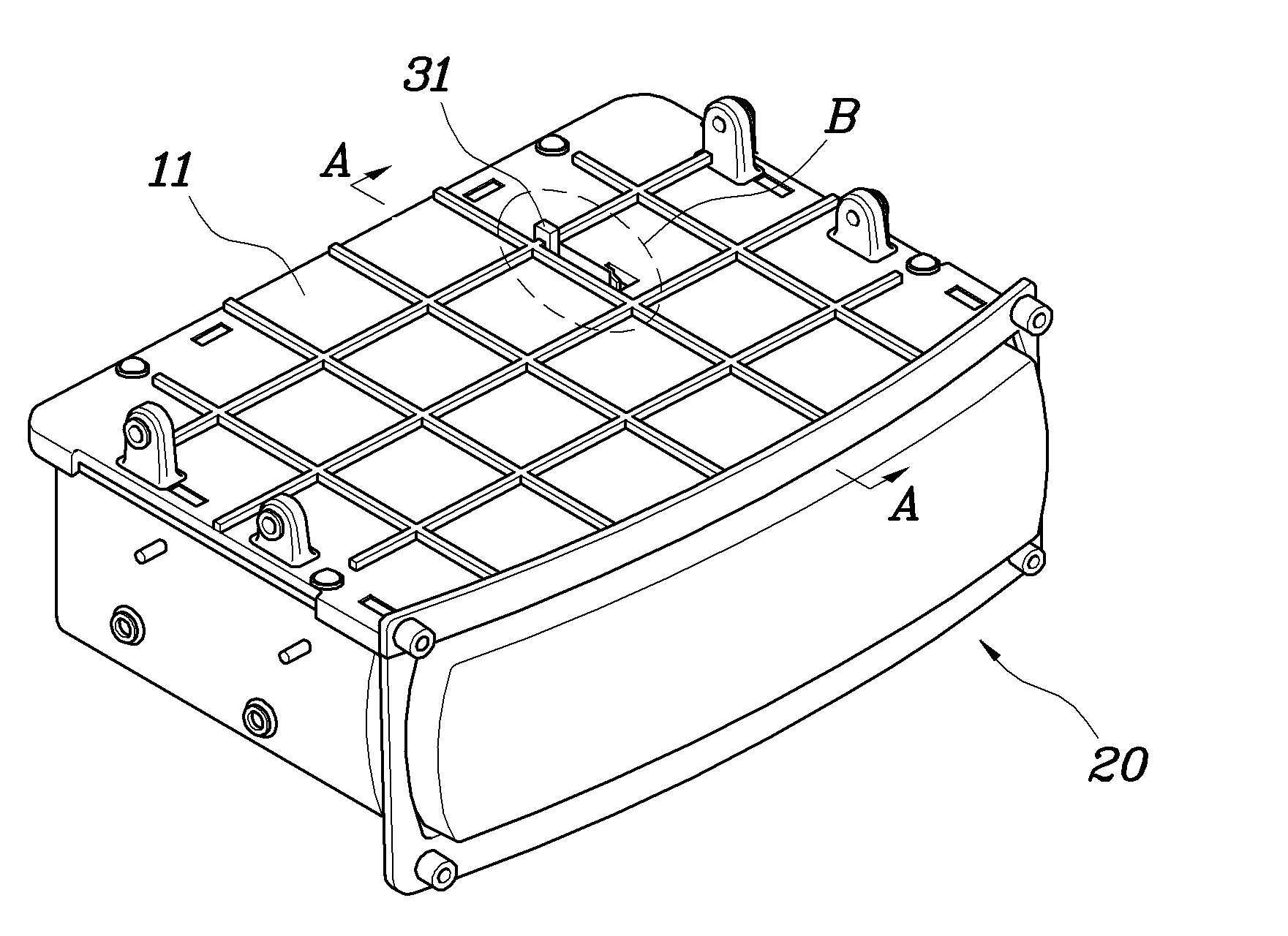
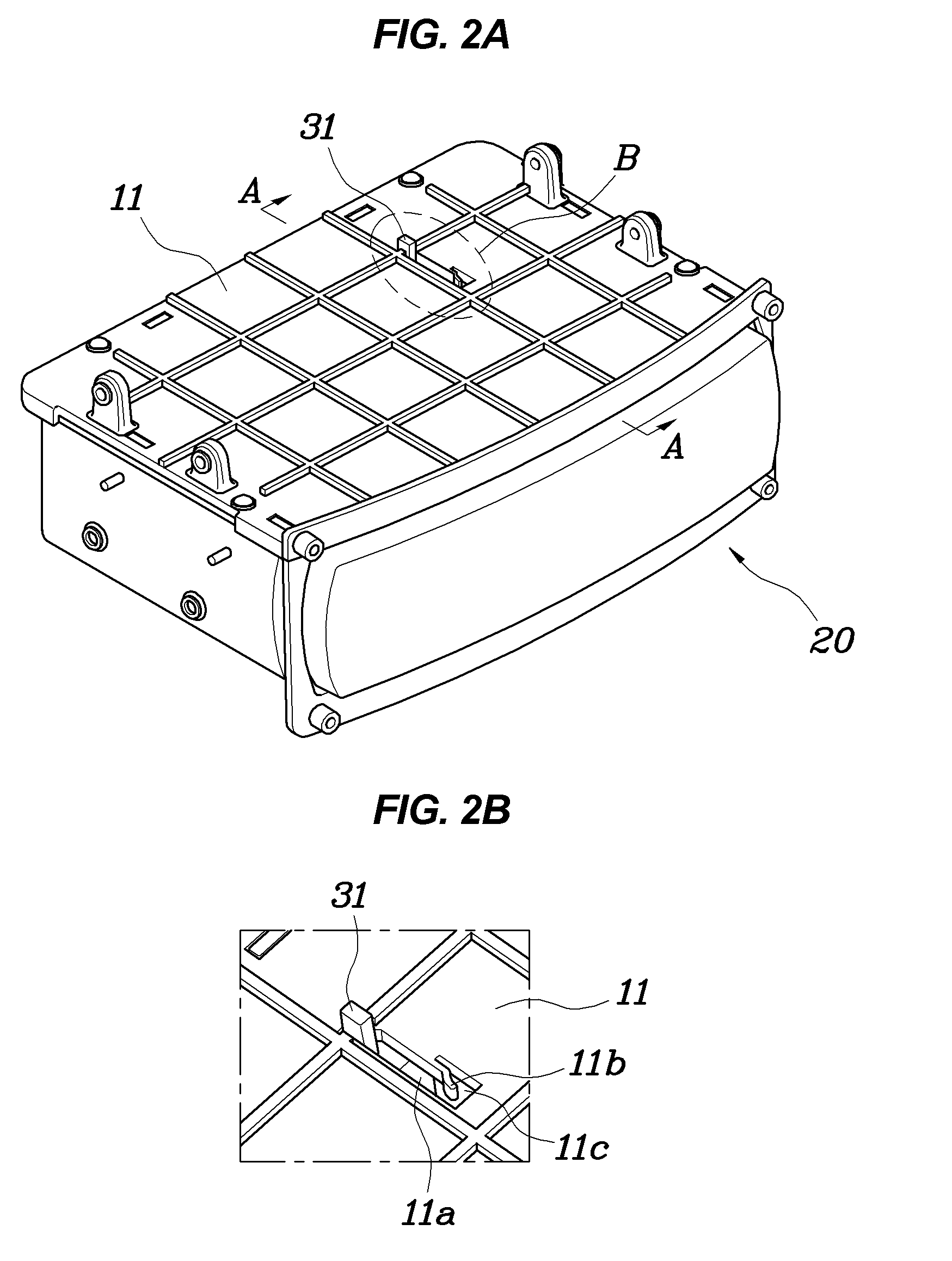
[0036]A tray apparatus according to various embodiments of the present invention will be described with reference to FIGS. 2A to 7.

[0037]Referring to FIGS. 2A to 3, the tray apparatus includes a housing 10 which is open at the front, and a tray 20 which is accommodated in the housing 10 to be opened and closed. When the front of the c...


PUM


Abstract

A tray apparatus may include a housing, a tray slidably accommodated in the housing to be opened or closed, a rotary lock pivotally coupled to the housing at a hinge portion of the rotary lock and locking the tray to the housing when external shock is applied to the tray beyond a predetermined value, wherein a center of gravity of the rotary lock is positioned above the hinge portion, and a holding unit for holding the rotary lock in a normal state so that the rotary lock maintains an original position thereof.

Description

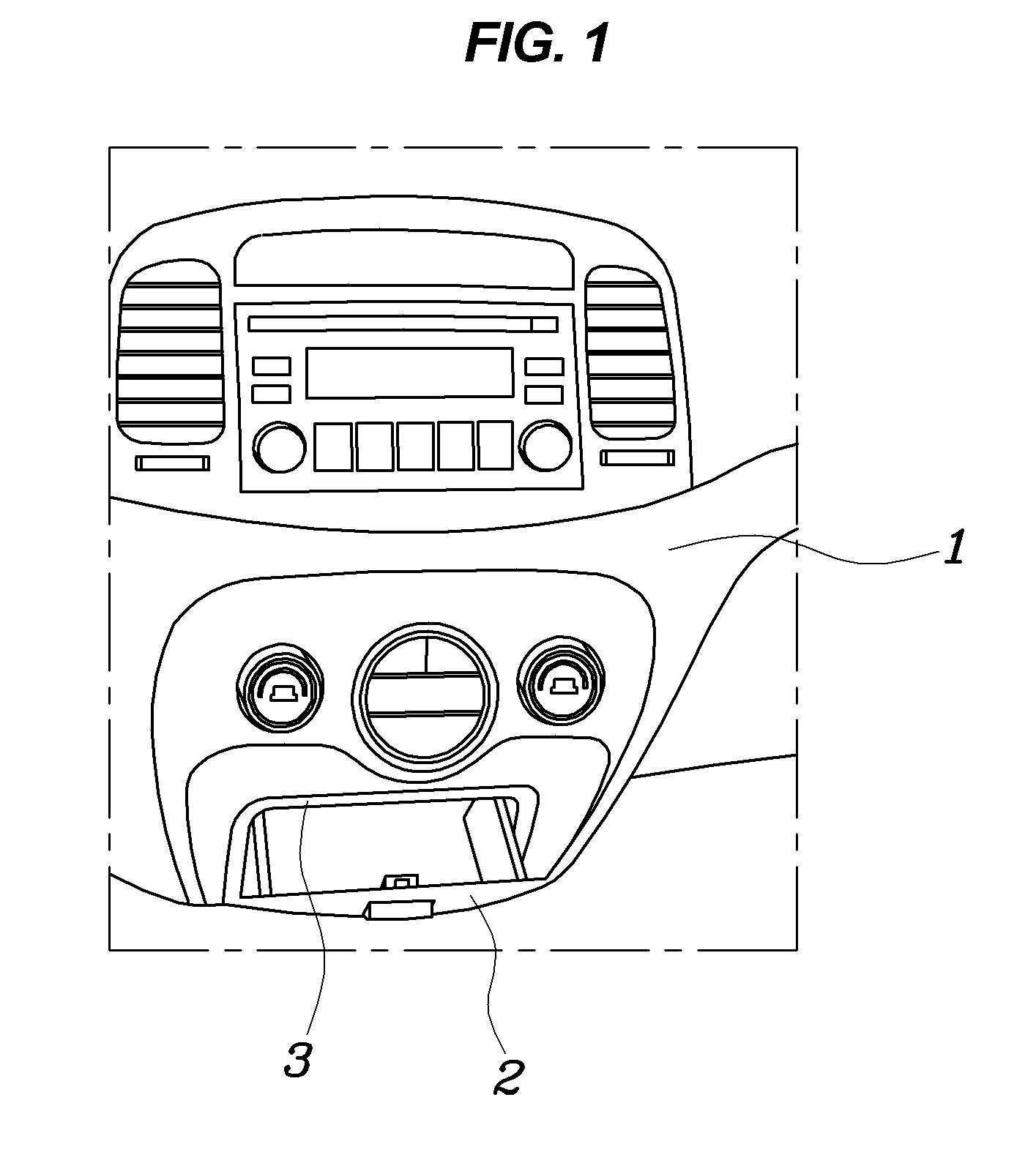
CROSS-REFERENCE TO RELATED APPLICATION[0001]The present application claims priority to Korean Patent Application Number 10-2008-0047438 filed May 22, 2008, the entire contents of which application is incorporated herein for all purposes by this reference.BACKGROUND OF THE INVENTION[0002]1. Field of the Invention[0003]The present invention relates to a tray apparatus, which prevents a tray, installed in a vehicle to hold articles, from unexpectedly opening due to external shocks.[0004]2. Description of Related Art[0005]In vehicle safety standards or regulations, there is a regulation pertaining to interior compartment doors and stating that trays installed in a vehicle must not open in a dummy crash test under given conditions, in order to ensure the safety of occupants.[0006]For example, referring to FIG. 1, showing a rotary tray apparatus, when the head of a dummy collides with a center fascia panel 1, a tray 2 mounted to the panel 1 must not open. To this end, a car maker mounts a...

Claims


Application Information

Patent Timeline
Patent Type & Authority Patents(United States)
IPC IPC(8): B60R7/06E05B77/04E05B83/30
CPCB60R7/04B60R7/06
Inventor LEE, JONG SUNLEE, YANG GISONG, TAE HOONKIM, IN GYUPARK, JIN WANKANG, YONG GU
Owner HYUNDAI MOTOR CO LTD
Why Eureka
Eureka Blog
Learn More