Rotary type pulse switch

a pulse switch and rotary type technology, applied in the direction of electric switches, electrical/magnetically converting sensor output, electrical apparatus, etc., can solve the problems of electrical components being damaged, static electricity picked up by the moving electrode, etc., and achieve the effect of high accuracy

Active Publication Date: 2008-04-17
HOSIDEN CORP
View PDF2 Cites 4 Cited by
  • Summary
  • Abstract
  • Description
  • Claims
  • Application Information

AI Technical Summary

Benefits of technology

[0014] Thus, the rotary type pulse switch provided by this invention is constructed such that, while securing required conduction between the movable electrode and fixed electrode, the movable electrode cannot easily pick up static electricity. This reduces the possibility of varied electrical components electrically connected to the movable electrode and fixed electrode being damaged by electrostatic discharge.
[0016] According to this characteristic construction, static electricity on the movable electrode can be released to the grounding means in times of the full insulation state. This further reduces the possibility of the varied electrical components electrically connected to the movable electrode and fixed electrode being damaged by electrostatic discharge.
[0020] According to this characteristic construction, the two or more contacted portions of the common fixed electrode pattern are arranged on the same circumference as the rotation locus as separated by the first fixed electrode pattern and second fixed electrode pattern. That is, the two or more contacted portions of the common fixed electrode pattern are arranged on the above circumference as opposed across the first fixed electrode pattern and second fixed electrode pattern. Since the common fixed electrode pattern is separated on the circumference, even when it is necessary to form in the middle part of the circumference other electrode patterns connected to the common fixed electrode pattern, the above other electrode patterns can be formed as connected to the separated parts of the common fixed electrode pattern. Therefore, the above common fixed electrode pattern and other electrode patterns are formed after being positionally adjusted by using each part of the common fixed electrode pattern. The electrode patterns are positioned with high accuracy.

Problems solved by technology

Thus, there is a problem that the movable electrode constantly picks up static electricity during the rotation.
The electrical components can be damaged by electrostatic discharge.

Method used


Image

  • Rotary type pulse switch
  • Rotary type pulse switch
  • Rotary type pulse switch

Examples


first embodiment

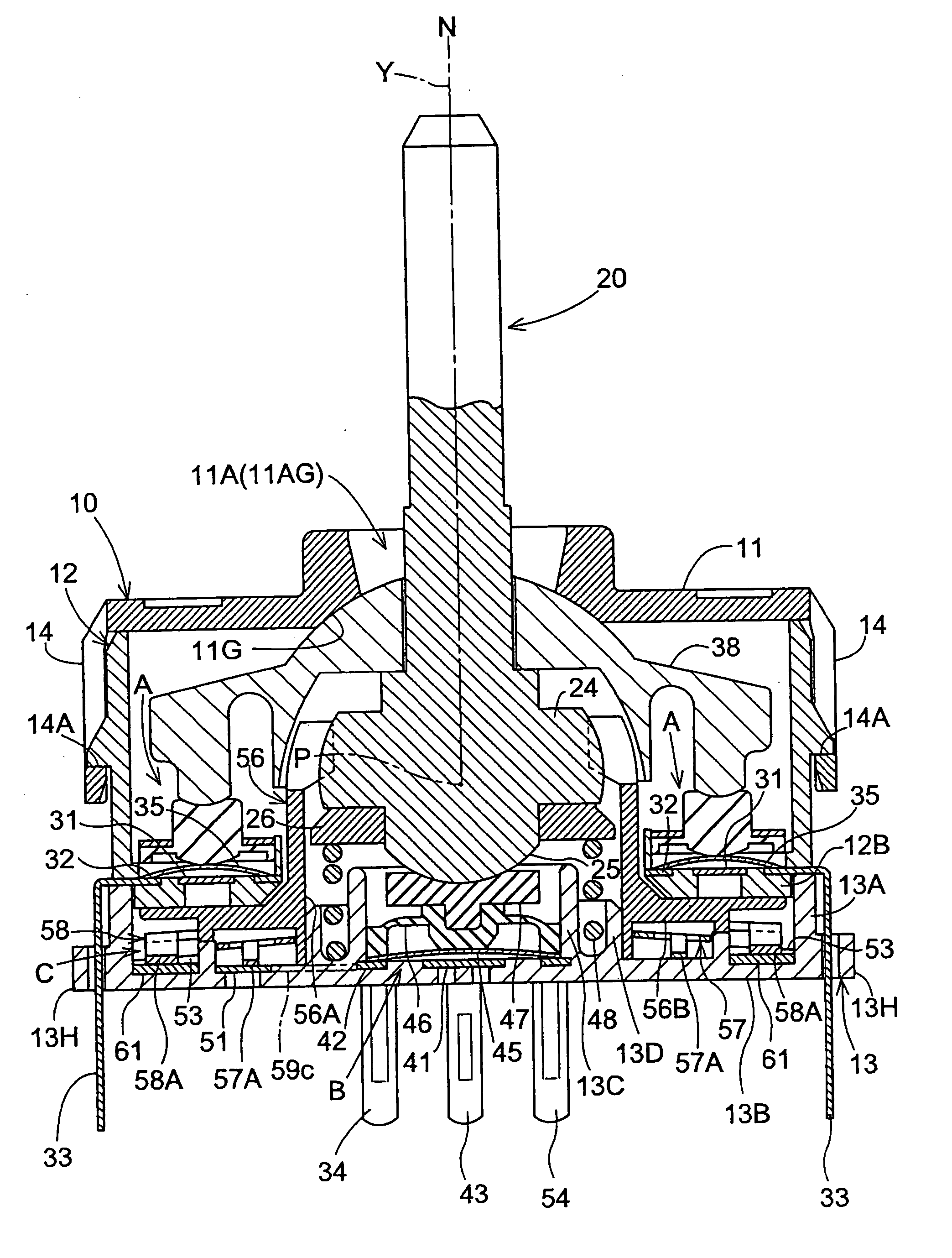
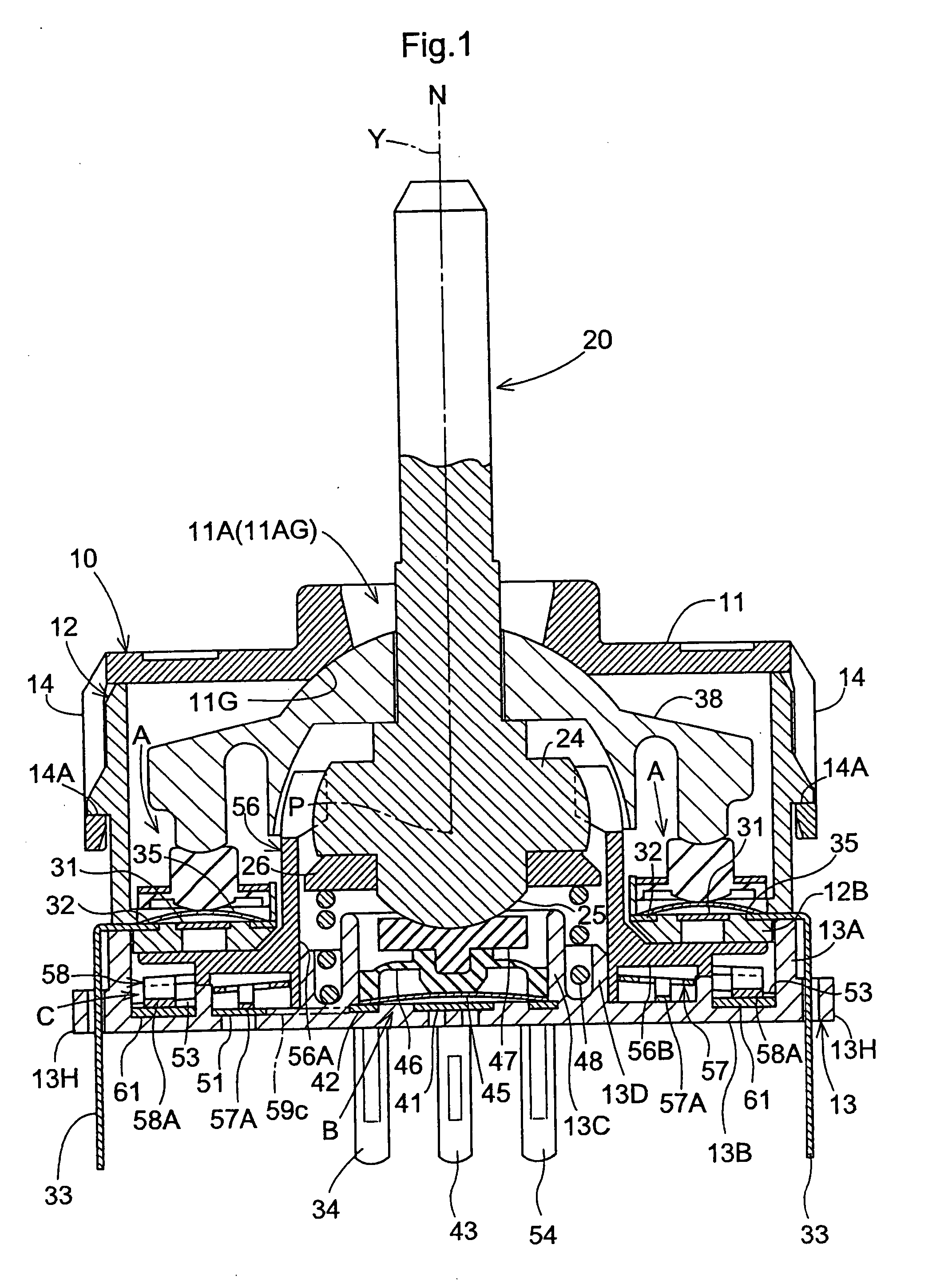
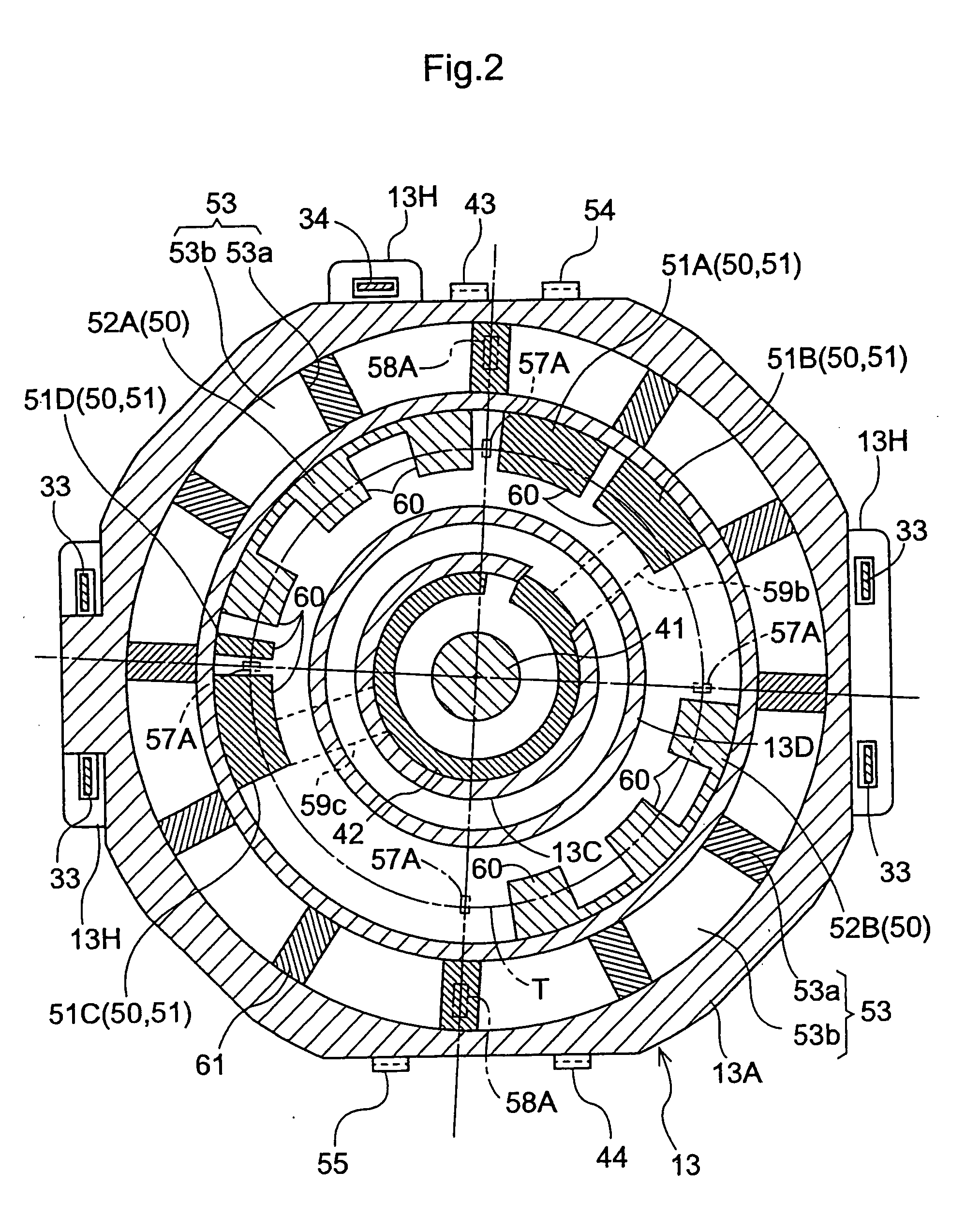
[0031] A rotary type pulse switch in a first embodiment will be described hereinafter with reference to the drawings. FIG. 1 is a side view in vertical section of the rotary type pulse switch. FIG. 2 is a view showing an arrangement of a fixed electrode on a bottom wall of a lower casing. FIG. 3 is a view showing a movable electrode on a rotor. FIG. 4 is an exploded perspective view of the rotor and movable electrode.

[0032] This rotary type pulse switch is included in combined control switches having an operating rod 20 extending vertically with respect to a case 10, a tilt detecting device A for electrically detecting tilting of the operating rod 20, a depression detecting device B for electrically detecting depression along an axis Y of the operating rod 20, and a rotation detecting device C for electrically detecting rotation of the operating rod 20. This combined control switch is provided for a control input unit of a mobile telephone, PDA, or game machine, or a control input ...

second embodiment

[0072] The rotary type pulse switch of the second embodiment is the same as the rotary type pulse switch of the first embodiment in the construction of the fixed electrode, but is different in the other mechanisms from the rotary type pulse switch of the first embodiment. The rotary type pulse switch of the second embodiment will be described hereinafter, omitting description of the same construction as in the first embodiment.

[0073]FIG. 7 is a top view of the rotary type pulse switch of the second embodiment. FIG. 8 is a view in vertical section of the rotary type pulse switch. FIG. 9 is an exploded perspective view of the rotary type pulse switch. FIG. 10 is a top view of a flexible substrate. As seen, the rotary type pulse switch of the second embodiment includes a first operating object 180 vertically movable relative to a case 110 to accept pushing operation. The first operating object 180 has a disk-like operating portion 181, and a depressing portion 182 formed on the lower ...


PUM


Abstract

A rotary type pulse switch includes a movable electrode 57 having a plurality of contacting portions 57A formed in positions of the same radius from its rotation center, and a fixed electrode 50 disposed face to face with the movable electrode 57 and having a plurality of contacted portions 60 arranged in form of stepping stones on the same circumference as a rotation locus T of the contacting portions 57A. The fixed electrode 50 includes a first fixed electrode pattern 52A, a second fixed electrode pattern 52B and a common fixed electrode pattern 51, each of the fixed electrode patterns 51, 52A, 52B being in a mutually nonconductive state. The contacted portions 60 are arranged in such a positional relationship that a full insulation state occurs during rotation of the movable electrode 57 in which none of the contacting portions 57A contact the first fixed electrode pattern 52A, second fixed electrode pattern 52B or common fixed electrode pattern 51.

Description

BACKGROUND OF THE INVENTION [0001] 1. Field of the Invention [0002] This invention relates to a rotary type pulse switch, and more particularly to a rotary type pulse switch comprising a movable electrode with a rotation center and having a plurality of contacting portions formed in positions of the same radius from the rotation center, and a fixed electrode disposed face to face with the movable electrode and having a plurality of contacted portions arranged in form of stepping stones on the same circumference as a rotation locus of the contacting portions of the movable electrode, wherein rotation information of the movable electrode is detected based on conduction states of the contacting portions and the contacted portions when the movable electrode is rotated. [0003] 2. Description of the Related Art [0004] Control input units of mobile telephones, PDAs and game machines, and control input units of home electric appliances, have rotary type pulse switches for detecting the rota...

Claims


Application Information

Patent Timeline
Patent Type & Authority Applications(United States)
IPC IPC(8): H01H19/00
CPCG01D5/25H01H19/585H01H19/005H01H19/02H01H19/28
Inventor ASADA, MAKOTO
Owner HOSIDEN CORP
Why Eureka
Try Eureka