Light Source Module

a technology of light source module and lamp base, which is applied in the direction of lighting and heating apparatus, lighting heating/cooling arrangements, transportation and packaging, etc., can solve the problems of increasing temperature and cooling demand, and achieve the effect of increasing the lifetime of the lamp and reducing the temperature at the lamp bas

Active Publication Date: 2008-04-17
MARTIN PROFESSIONAL
View PDF10 Cites 4 Cited by
  • Summary
  • Abstract
  • Description
  • Claims
  • Application Information

AI Technical Summary

Benefits of technology

[0011]The object of the present invention is to reduce the temperature at the lamp base to increase the lifetime of a lamp. A furth...

Problems solved by technology

Even if there is sufficient capacity of the heat sink surrounding the dechroic reflector, heat will be transmitted through the lamp t...

Method used


Image

  • Light Source Module
  • Light Source Module
  • Light Source Module

Examples


Embodiment Construction

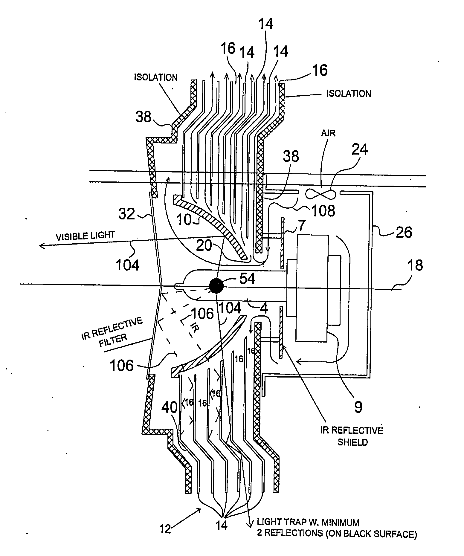
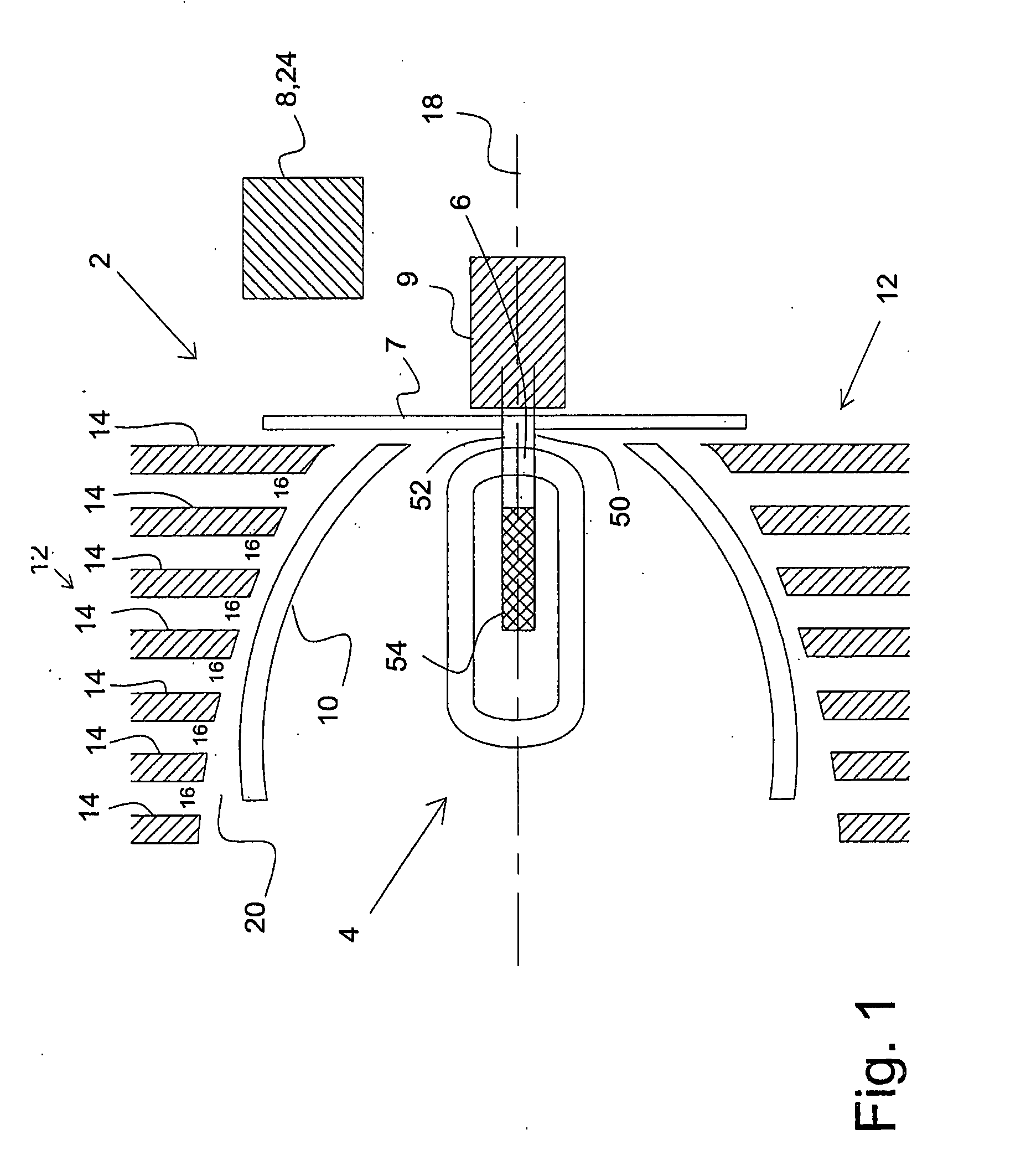
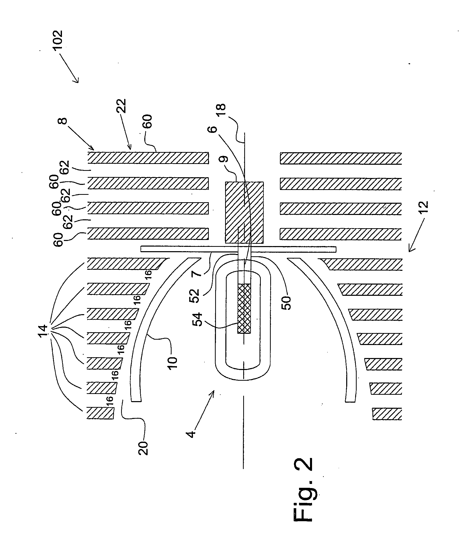
[0030]FIG. 1 shows a light source module 2 comprising a light source 4 connected to a light source base 6 where a reflector 7 is placed between the light source 4 and the light source base 6. Cooling means 8 for cooling the light source base 6 is shown which could be in form of means 24 for generating forced air, or a kind of passive means could be used. A lamp socket 9 is connected to the lamp base 6. A dechroic reflector 10 partly surrounds the light source 4 where a heat sink 12 is shown outside the reflector 10. The heat sink 12 is formed of a number of dishes 14 between which dishes 14, air gabs 16 exist. The dishes 14 and also the air gabs 16 are orientated perpendicularly to the centre axis 18 of the light source 2. Between the dishes 14 and the dechroic reflector 10, an air gab 20 is shown.

[0031]In operation, the light source module 2 will operate in that the light source 4 generates light which light contains visible light but also have a great amount of infrared light. The...


PUM


Abstract

The present invention relates to a light source module comprising a light source, which light source module comprises cooling means for cooling the light source base, which light source module further comprises a dechroic reflector, where at least one heat sink surrounds the dechroic reflector. The object of the present invention is to reduce the temperature at the lamp base to increase the lifetime of a lamp. This can be achieved by a light source module that comprises at least a first heat sink, which first heat sink comprises a number of dishes, which dishes are formed to achieve air gabs there between, which dishes comprises at least one opening for the dechroic reflector, which dishes are placed radially around the dechroic reflector, which air gabs between the dishes are directed mostly perpendicularly to a centre axis of the light source module. Hereby, it is achieved that most of the infrared light, which is radiated in the direction of the dechroic reflector is absorbed in the dishes of the heat sink, and because the direction of the dishes is perpendicular to the main axis of the lamp module, the dishes conduct the heat radially towards the outer surface of the dishes.

Description

BACKGROUND OF THE INVENTION[0001]1. Filed of the Invention[0002]The present invention relates to a light source module comprising a light source, which light source is connected by a light source base, which light source module comprises cooling means for cooling the light source base, which light source module further comprises a dechroic reflector, where at least one heat sink surrounds the dechroic reflector.[0003]2. Description of Related Art[0004]Reducing the pinch temperature of a light source base at least with lamps having a filament is very important. The filament is connected by electric conductive means through the lamp closure and through the lamp base. Increasing temperature leads to an oxidation and corrosion of the electric conductors. This leads to a reduction of the lifetime of the lamp. Therefore, the temperature at the pitch must typically be reduced to a temperature below 450-500 degrees C.[0005]U.S. Pat. No. 5,626,416 describes a lamp module apparatus comprising...

Claims


Application Information

Patent Timeline
IPC IPC(8): F21V29/00F21V19/02F21V29/02F21V29/15
CPCF21V19/02F21V29/004F21V29/02F21V29/83F21V29/75F21V29/767F21V29/15F21V29/677F21V29/70
Inventor RASMUSSEN, NIELS J&OSLASH, RGENGLAVIND, MADS
Owner MARTIN PROFESSIONAL
Why Eureka
Try Eureka