Video-signal processing method, program of video-signal processing method, recording medium having recorded thereon program of video-signal processing method, and video-signal processing apparatus

a video signal and processing method technology, applied in the field programs of video signal processing methods, recording media, can solve the problems of insufficient noise suppression, insufficient noise level measurement, blurring at object boundaries, etc., to achieve the effect of avoiding noise level measurement, reducing noise level, and improving noise level measurement accuracy

Inactive Publication Date: 2008-05-08
SONY CORP
View PDF6 Cites 16 Cited by
  • Summary
  • Abstract
  • Description
  • Claims
  • Application Information

AI Technical Summary

Benefits of technology

[0018] With the first video-signal processing method, program, recording medium, or video-signal processing apparatus, noise level can be measured with regions having extremely small noise levels excluded from subjects of noise level measurement. For example, it is possible to refrain from measuring noise level in regions of graphical user interfaces of a television receiver, an optical disc recorder, or the like, or regions of caption information or the like added during editing. Thus, the level of noise mixed into video content signals can be measured accurately, so that the accuracy of noise-level measurement can be improved.
[0019] With the second video-signal processing method, program, recording medium, or video-signal processing apparatus, by effectively using correlation with neighboring pixels, noise level can foe measured with regions having extremely small noise levels excluded from subjects of noise level measurement. For example, it is possible to refrain from measuring noise level in regions of graphical user interfaces of a television receiver, an optical disc recorder, or the like, or regions of caption information or the like added during editing. Thus, the level of noise mixed into video content signals can be measured accurately, so that the accuracy of noise-level measurement can be improved.
[0020] According to these embodiments of the present invention, the accuracy of noise-level measurement can be improved.

Problems solved by technology

Thus, when the level of the correction signal is too large, blurring occurs at object boundaries, texture regions, or the like.
Conversely, when the level of the correction signal is too small, noise is not suppressed sufficiently.
However, existing methods are not practically sufficient to measure noise level accurately.
Thus, it has been difficult to remove noise appropriately.

Method used


Image

  • Video-signal processing method, program of video-signal processing method, recording medium having recorded thereon program of video-signal processing method, and video-signal processing apparatus
  • Video-signal processing method, program of video-signal processing method, recording medium having recorded thereon program of video-signal processing method, and video-signal processing apparatus
  • Video-signal processing method, program of video-signal processing method, recording medium having recorded thereon program of video-signal processing method, and video-signal processing apparatus

Examples


first embodiment

(1) Configuration of the Embodiment

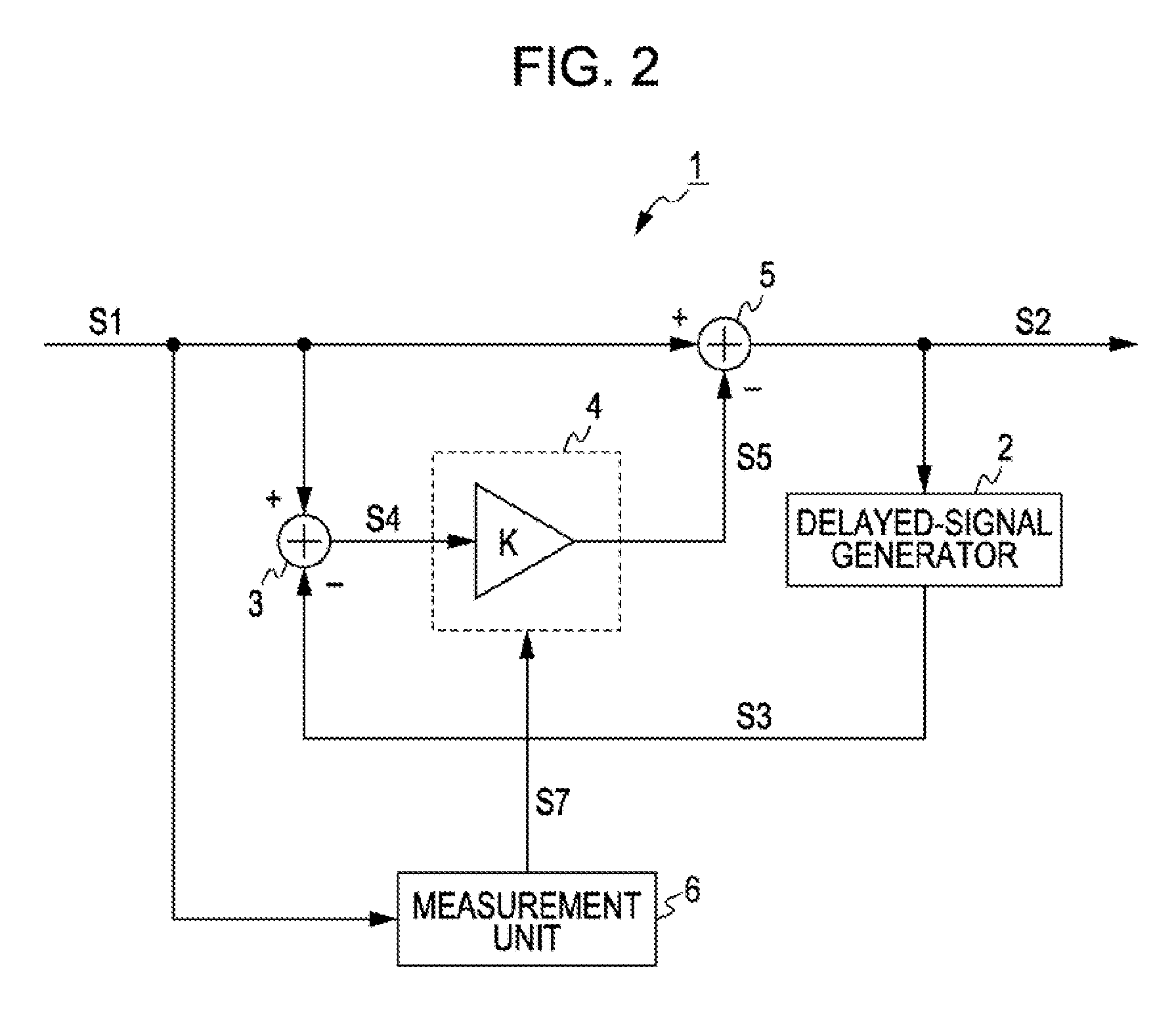
[0084]FIG. 2 is a block diagram of a noise filter used, in a video-signal processing apparatus according to an embodiment of the present invention. Referring to FIG. 2, a noise filter 1 is an infinite-impulse-response (IIR) noise filter. By effectively using correlation between successive fields or frames, the noise filter 1 removes noise from an input video signal S1 to output an output video signal S2.

[0085] More specifically, a delayed-signal generator 2 delays the output, video signal S2 to output a delayed signal S3 for extracting a noise component. Alternatively, the delayed signal S3 may be generated by motion-compensation of the output, video signal S2. A subtracting circuit 3 subtracts the delayed video signal S3 from the input video signal S1 to generate a noise signal component S4. A signal-level correcting circuit 4 corrects the signal level of the noise signal component S4 to generate a correction signal S5. A subtracting circuit 5 s...

second embodiment

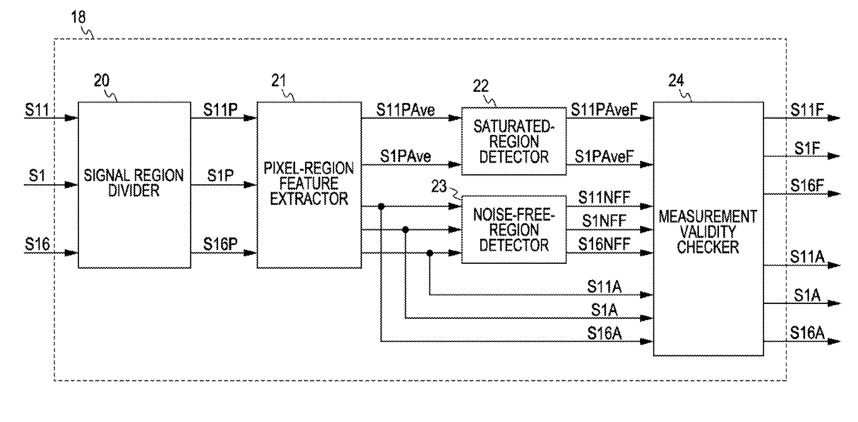
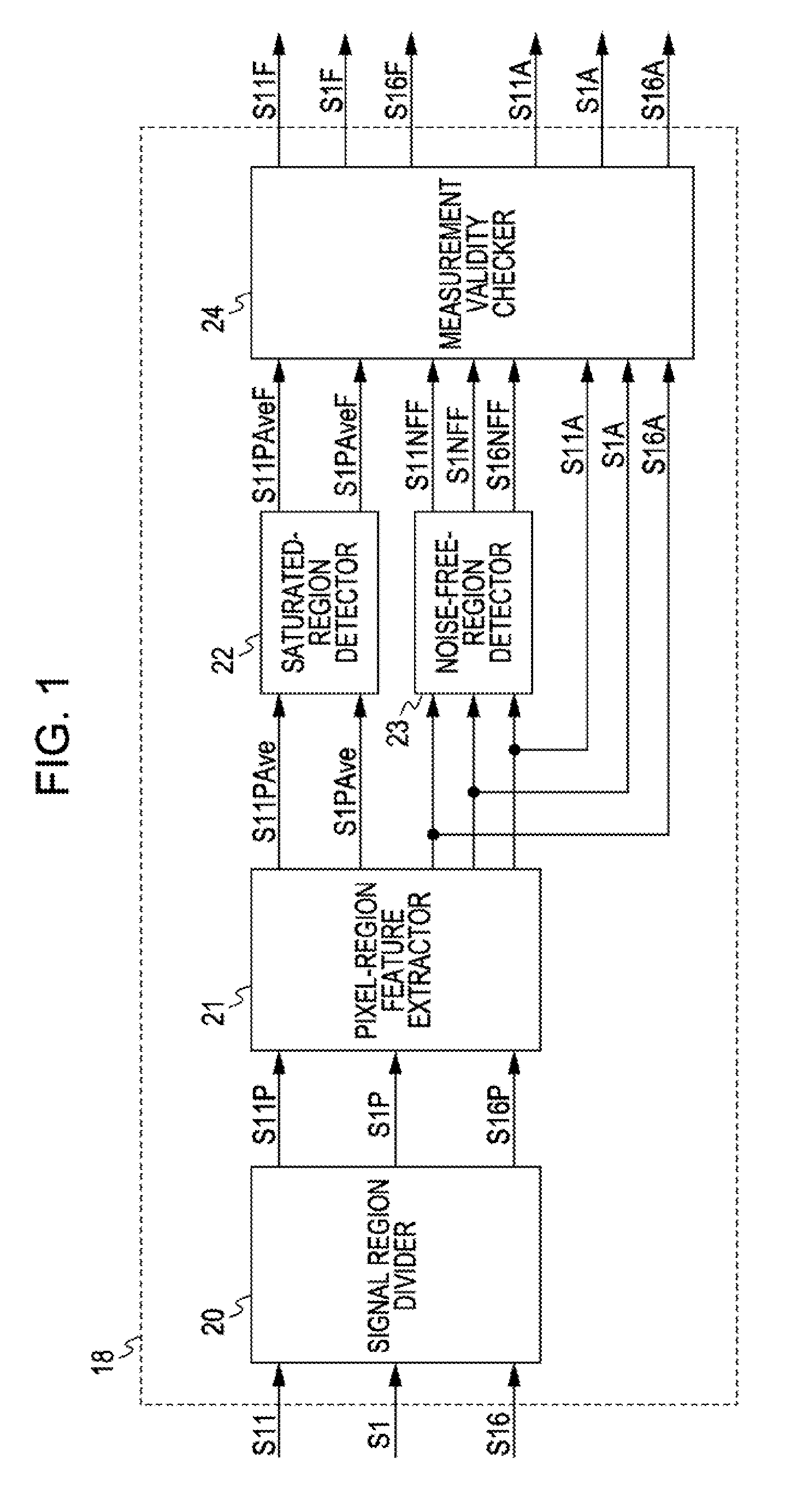
[0151]FIG. 14 is a block diagram showing the configuration of a noise-region detector in a noise filter according to a second embodiment of the present invention. The noise filter according to the second embodiment is configured the same as the noise filter according to the first, embodiment except in that a noise-region detector 51 is used instead of the noise-region detector 18. In the following description, parts corresponding to those in the first embodiment are designated by the same numerals, and repeated description thereof will be refrained.

[0152] In the noise-region detector 51, instead of setting the flags S1PAveF and S11PAveF so that white-level-side regions and black-level-side regions where noise could have been suppressed are excluded from noise-level measurement, the activities S1A, S11A, and S16A are corrected to indicate noise levels before noise suppression so that these regions can also be used for noise-level measurement. Similarly to the noise-region detector 1...

third embodiment

[0159] With the configuration according to the first embodiment, depending on the nature of the input video signal S1, the noise-free-region detection flags S1NFF, S11NFF, and S16NFF are turned on in most regions, so that the number of regions used for noise-level measurement becomes extremely small. This could degrade the confidence of measurement results.

[0160] Thus, in a third embodiment of the present invention, when the number of regions for which the noise-free-region detection flags S1NFF, S11NFF, and S16NFF are turned on increases, the number of regions excluded from noise-level measurement on the basis of the minimum activity MinAct is reduced. In the following description, parts corresponding to those in the first and second embodiments are designated by the same numerals, and repeated description thereof will be omitted.

[0161]FIG. 18 is a block diagram showing the configuration of a measurement-validity checker in a noise filter according to the third embodiment of the ...


PUM


Abstract

A video-signal processing method for measuring a noise level of an input video signal includes the steps of detecting an intra-field or intra-frame feature for each region that, is set in the input video signal, the intra-field or intra-frame feature representing a noise level in the input video signal within a field or frame; checking the intra-field or intra-frame feature against a noise-free-region threshold, and excluding regions with which the infra-field or intra-frame feature is less than the noise-free-region threshold from subjects of noise-level measurement; and outputting a result of noise-level measurement by statistically processing the intra-field or intra-frame features of regions remaining without being excluded.

Description

CROSS REFERENCES TO RELATED APPLICATIONS [0001] The present invention contains subject matter related to Japanese Patent Application JP 2006-156936 filed in the Japanese Patent Office on Jun. 6, 2006, and Japanese Patent Application JP 2007-108947 filed in the Japanese Patent Office on Apr. 18, 2007, the entire contents of which are incorporated herein by reference. BACKGROUND OF THE INVENTION [0002] 1. Field of the Invention [0003] The present invention relates to video-signal processing methods, programs of video-signal processing methods, recording media having recorded thereon programs of video-signal processing methods, and video-signal processing apparatuses. For example, the present invention can be applied to noise filters that reduce noise in video signals. According to the present invention, regions with extremely small noise levels are excluded from subjects of noise-level measurement. Thus, the accuracy of noise-level measurement car, be improved. [0004] 2. Description o...

Claims


Application Information

Patent Timeline
Patent Type & Authority Applications(United States)
IPC IPC(8): H04N17/00H04N5/00
CPCH04N17/00H04N5/21H04N5/213
Inventor KIMURA, SEIJIOGATA, MASAMI
Owner SONY CORP
Why Eureka
Try Eureka