Video signal processing method, program for the video signal processing method, recording medium recording the program for the video signal processing method, and video signal processing apparatus
- Summary
- Abstract
- Description
- Claims
- Application Information
AI Technical Summary
Benefits of technology
Problems solved by technology
Method used
Image
Examples
first embodiment
[0066](1) Configuration of the Embodiment
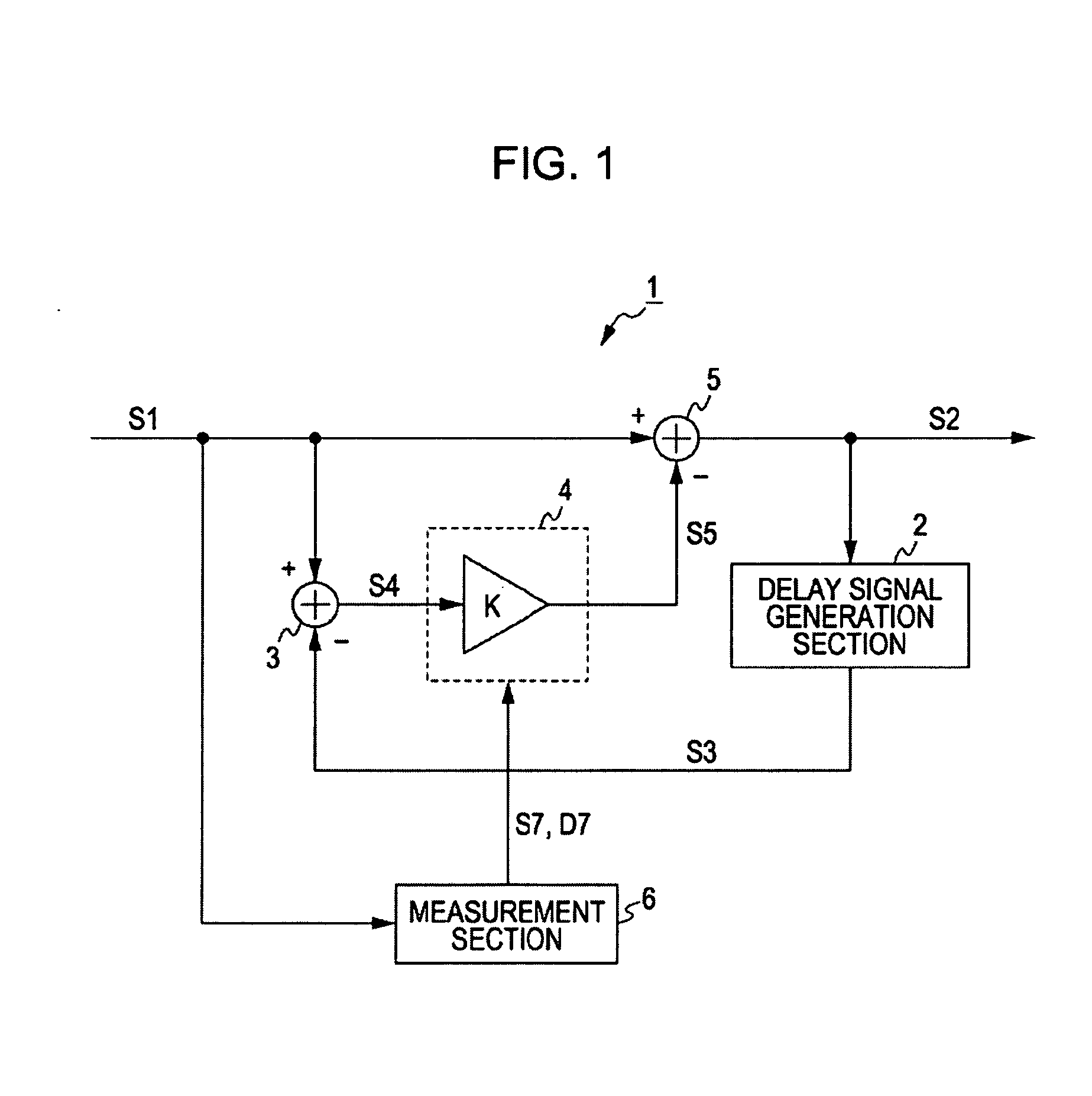
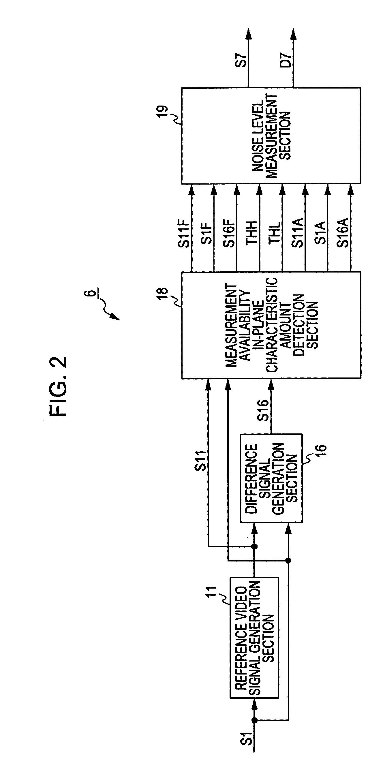
[0067]FIG. 1 is a block diagram of a noise filter which is applied to a video signal processing apparatus according to a first embodiment of the present invention. A noise filter 1 is a time cyclic noise filter and adapted to eliminate a noise of an input video signal S1 by utilizing a correlation between continuous fields and frames to output an output video signal S2.
[0068]It should be noted that according to this embodiment, the noise filter 1 is configured of a processor adapted to process the input video signal S1 through an execution of a predetermined program. According to this embodiment, this program is previously installed and provided but instead of this, the program may also be recorded and provided in a recording medium such as an optical disk, a magnetic disk, or a memory card or provided through a download via a network such as the Internet.
[0069]Herein, a delay signal generation section 2 is adapted to delay the output video s...
second embodiment
[0173]FIG. 36 is a block diagram of a configuration of a noise distribution characteristic amount calculation section applied to the video signal processing apparatus according to a second embodiment of the present invention. The video signal processing apparatus according to the second embodiment is configured similarly to the noise filter 1 according to the first embodiment except that a noise distribution characteristic amount calculation section 68 is applied instead of the noise distribution characteristic amount calculation section 38 (FIGS. 16 and 24) and a distribution reliability degree setting section 81 which will be described later is applied instead of the distribution reliability degree setting section 51 (FIGS. 15 and 27).
[0174]Herein, in the noise distribution characteristic amount calculation section 68, a peak neighborhood range setting section 71 is provided instead of the peak neighborhood lower position detection section 41 and the peak neighborhood upper positi...
third embodiment
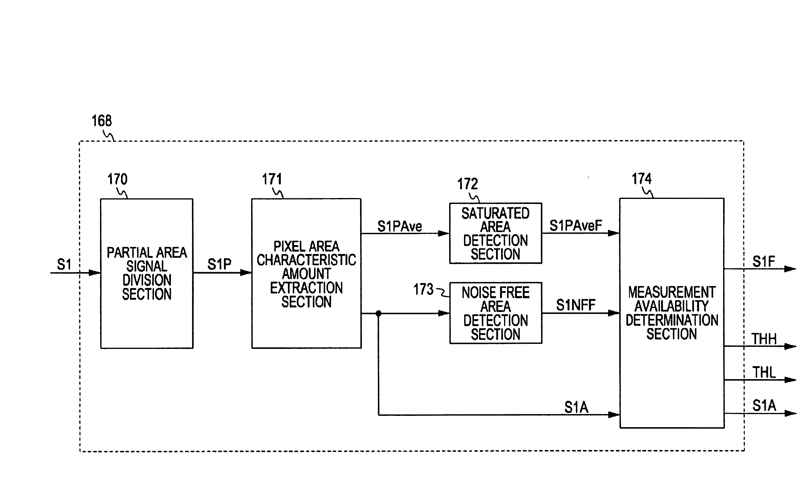
[0182]FIG. 41 is a block diagram of a measurement section 96 applied to the video signal processing apparatus according to a third embodiment. The video signal processing apparatus according to this embodiment has a similar configuration to the noise filter 1 according to the first embodiment except that a measurement noise level delay section 99 is provided, and a measurement availability in-plane characteristic amount detection section 98 is provided the measurement availability in-plane characteristic amount detection section 18.
[0183]Herein, the measurement noise level delay section 99 is adapted to delay the measurement result S7 which is output from the noise level measurement section 19 by the period of the one field or the one frame to be output.
[0184]The measurement availability in-plane characteristic amount detection section 98 has a similar configuration to the above-mentioned measurement availability in-plane characteristic amount detection section 18 in FIG. 6 except t...
PUM
 Abstract
Description
Claims
Application Information
 - R&D
- Intellectual Property
- Life Sciences
- Materials
- Tech Scout
- Unparalleled Data Quality
- Higher Quality Content
- 60% Fewer Hallucinations
Browse by: Latest US Patents, China's latest patents, Technical Efficacy Thesaurus, Application Domain, Technology Topic, Popular Technical Reports.
© 2025 PatSnap. All rights reserved.Legal|Privacy policy|Modern Slavery Act Transparency Statement|Sitemap|About US| Contact US: help@patsnap.com


