Methods and systems for blending between stereo and mono in a FM receiver

a stereo receiver and stereo technology, applied in the field of stereo receivers, can solve the problems of increased noise level and noise in the fm broadcast band receiver, and achieve the effects of reducing lr gain, maintaining and maximizing audio snr, and reducing total nois

Active Publication Date: 2013-04-09
SKYWORKS SOLUTIONS INC
View PDF3 Cites 5 Cited by
  • Summary
  • Abstract
  • Description
  • Claims
  • Application Information

AI Technical Summary

Benefits of technology

[0006]Disclosed herein are methods and systems for blending the audio output from a received FM signal (e.g., about 76 MHz to 108 MHz) between stereo and mono. Using the disclosed methods and systems, the L−R (left-minus-right) gain of the FM MPX may be adjusted as a function of RF SNR and the L+R (left-plus-right) noise level. In particular, given that the audio noise in both the L−R and L+R signals increases (e.g., on a dB by dB basis) as the RF SNR decreases, the disclosed methods and systems may be implemented to reduce the L−R gain based on the RF SNR and L+R noise in a manner such that the total noise is kept substantially constant throughout the stereo-to-mono blend region. In one exemplary embodiment, adjusting the L−R gain in this manner allows blending to be initiated at a lower RF level such that audio output of a FM stereo receiver remains in full stereo separation mode down to a lower RF signal level (and to a lower RF SNR) than is possible using prior art blending methods without exceeding a given NT and while maintaining and maximizing audio SNR. A further advantage of the disclosed methods and systems is that noise level in the audio output increases in a substantially monotonic manner such that the increasing noise in the audio output is less objectionable and a better listening experience is provided than as is the case with prior art blending techniques.

Problems solved by technology

FM broadcast band receivers can suffer from noise due to strong nearby blockers and / or other sources or conditions, and this noise or interference will often show up as static in the stereo audio output for the tuned FM channel.
The consequence of this hump is increased noise level in parts of the blend region closer to LS while audio output is in full or partial stereo mode.

Method used


Image

  • Methods and systems for blending between stereo and mono in a FM receiver
  • Methods and systems for blending between stereo and mono in a FM receiver
  • Methods and systems for blending between stereo and mono in a FM receiver

Examples


embodiment 100

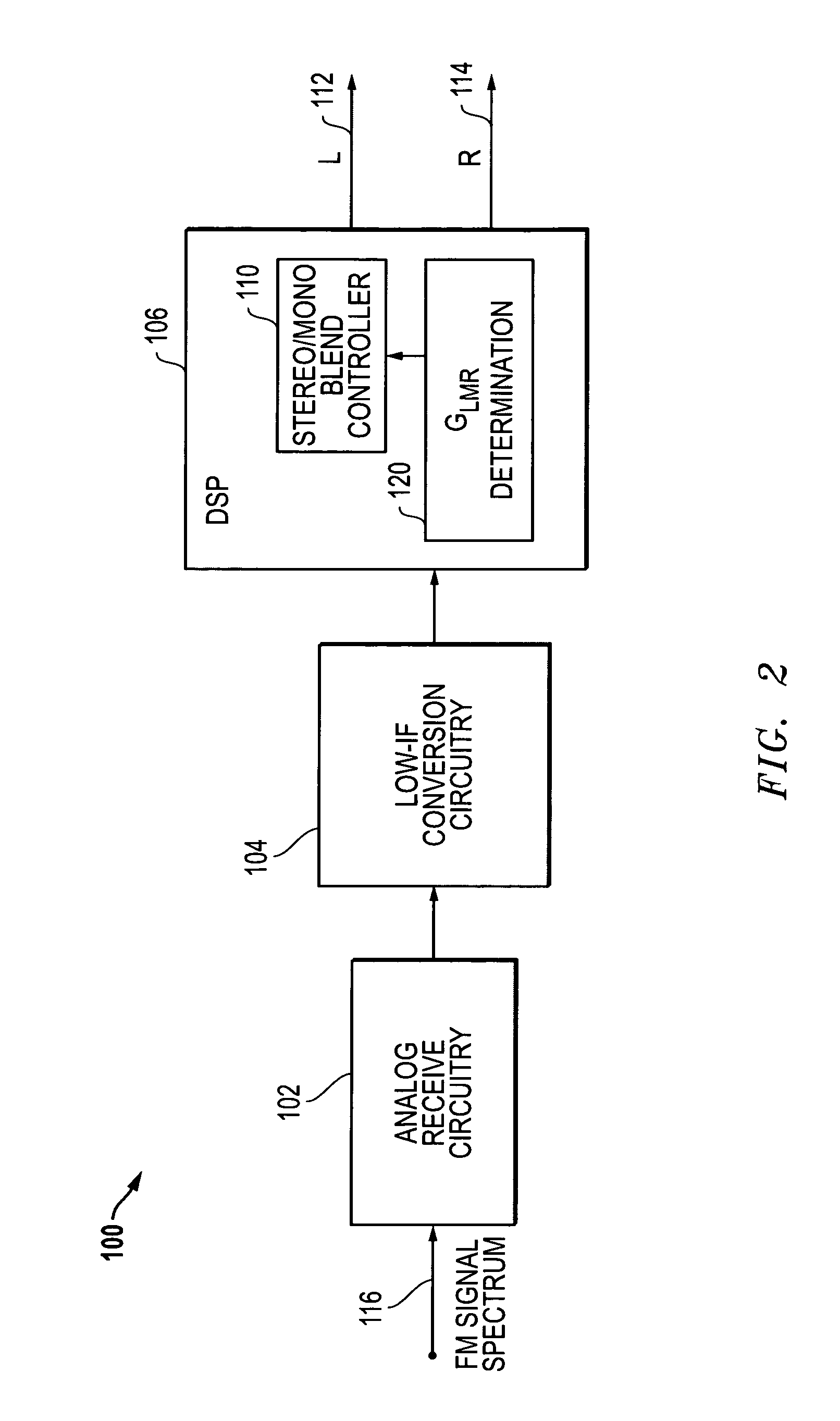
[0017]FIG. 2 is a block diagram for an embodiment 100 including a digital signal processor (DSP) 106 that controls blending between stereo and mono audio output, for example, in a FM receiver. In the embodiment depicted, an FM signal spectrum 116 including a plurality of FM channels is received by analog receive circuitry 102. The output of the analog receive circuitry 102 is provided to the low-IF conversion circuitry 104. The digital output of the low-IF conversion circuitry is then processed by the DSP 106 to produce digital and / or analog audio output signals. For example, the DSP 106 can produce stereo output signals in the form of a left (L) channel signal 112 and a right (R) channel signal 114.

[0018]As described herein, the DSP 106 further provides for processing of the digital signals to blend between stereo and mono based on a determined L−R gain value (GLMR), which is equivalent to k in the stereo blending equation. As described above, a mono output is typically created by ...

embodiment 400

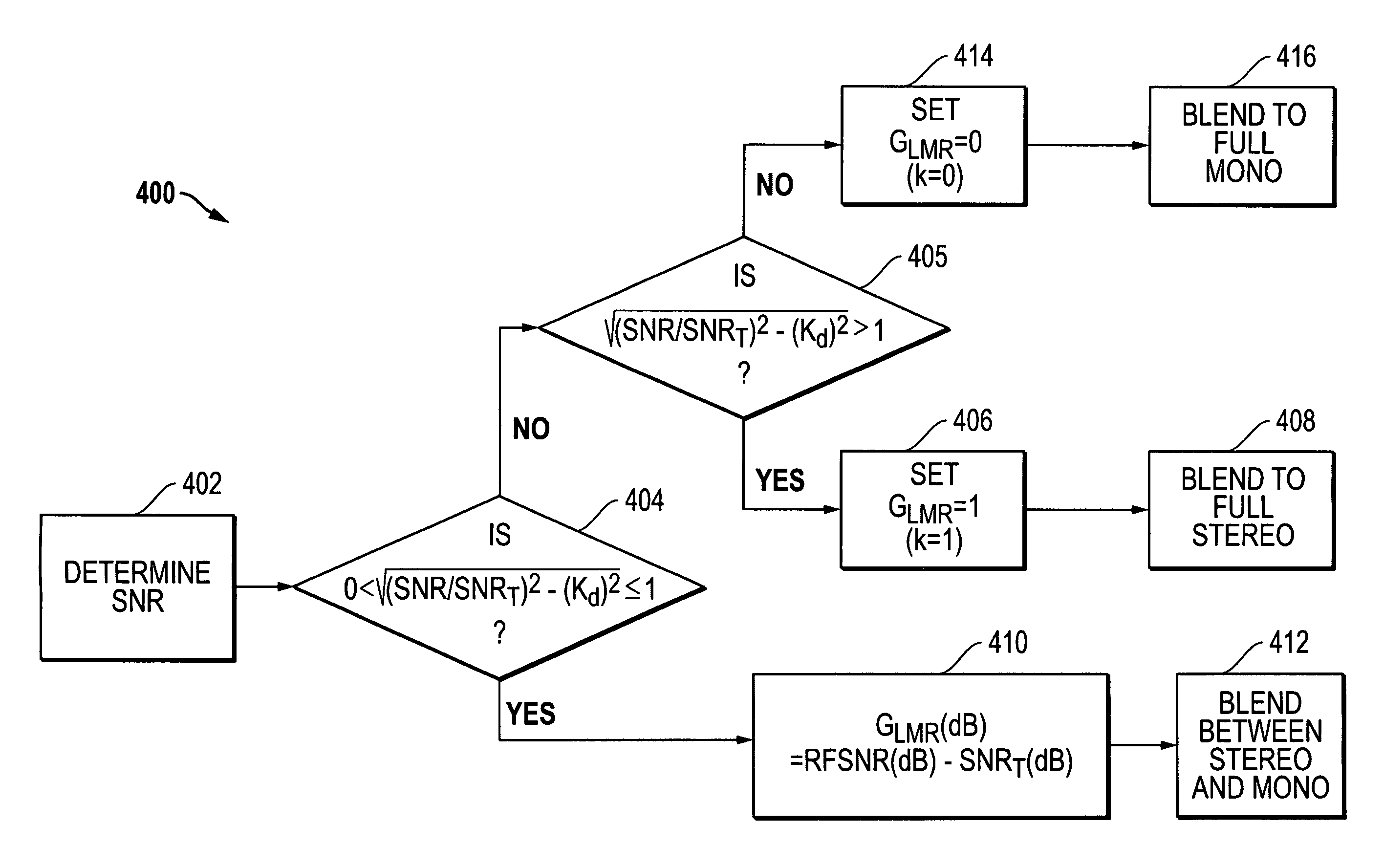
[0055]FIG. 5 is a flow diagram of an embodiment 400 for determining GLMR and blending from stereo to mono based upon the GLMR determination. As shown in FIG. 5, the SNR of the received FM broadcast signal is determined in block 402. Next, in step 404, the value of √{square root over ((SNR / SNRT)2−(Kd)2)}{square root over ((SNR / SNRT)2−(Kd)2)} is determined. Kd is the ratio of the output signal including the L−R energy to the output signal including the L+R energy, and SNRT may be, for example, a pre-selected RF SNR value that corresponds to a selected audio noise SNR threshold below which blending away from full stereo is desired. SNRT may be selected, for example, from an empirical correlation of audio noise SNR values versus corresponding RF SNR values derived from testing of the RF receiver circuitry. Table 1 is an example correlation of audio noise SNR values versus corresponding RF SNR values, in which there is a 1:1 relationship between audio SNR and RF SNR. Although such a line...


PUM


Abstract

Methods and systems for blending the audio output from a received FM signal between stereo and mono in which the L−R (left-minus-right) gain of the FM MPX may be adjusted as a function of RF signal to noise ratio (SNR) and the L+R (left-plus-right) noise level. During blending, the L−R gain based on the RF SNR and L+R noise may be reduced in a manner such that the total noise is kept substantially constant throughout the stereo-to-mono blend region.

Description

FIELD OF THE INVENTION[0001]This invention relates to stereo receivers and, more particularly, to stereo / mono blending during playback of FM stereo broadcasts.BACKGROUND OF THE INVENTION[0002]Broadcast channels in the FM band (e.g., about 76 MHz to 108 MHz) are often transmitted with an FM stereo multiplex (MPX) format where the MPX signal includes left (L) channel and right (R) channel information that can then be used by an FM receiver to produce stereo audio outputs. In particular, the FM stereo MPX signal format includes L+R (left-plus-right) information, L−R (left-minus-right) information and a 19 KHz pilot tone. With respect to the center frequency of the broadcast channel, the L+R information lies in a band between 30 Hz and 15 KHz from the center frequency in the broadcast channel. The L−R information lies in two bands on either side of 38 KHz from the center frequency of the broadcast channel, namely a first band between 23 KHz and 38 KHz and a second band between 38 KHz an...

Claims


Application Information

Patent Timeline
Patent Type & Authority Patents(United States)
IPC IPC(8): H04B1/30
CPCH04B1/1676H04H40/81
Inventor ALLEN, JOHN L.ELENES, JAVIERCHAMPAGNE, GERALD D.
Owner SKYWORKS SOLUTIONS INC
Why Eureka
Try Eureka