
Methods and systems for extending electric idle

a technology of electric idle and extended time, applied in the direction of battery/fuel cell propulsion, battery/cell control arrangement, transportation and packaging, etc., can solve the problem of not being able to restart the engine, etc., and achieve the effect of prolonging the electric idle duration, reducing the number of times, and extending or reducing the amount of charg

Active Publication Date: 2018-07-03
FORD GLOBAL TECH LLC
View PDF11 Cites 0 Cited by
  • Summary
  • Abstract
  • Description
  • Claims
  • Application Information

AI Technical Summary

Benefits of technology

[0004]By estimating whether or not a future vehicle electric idle will exceed a threshold energy consumption amount and adjusting a value of a battery target or desired state of charge based on the estimate of exceeding the threshold energy consumption amount, it may be possible to extend an electric idle duration and reduce a number of times a vehicle's engine is restarted while the vehicle is stationary. Alternatively, an estimate of a threshold electric idle time duration may be provided and the electric energy storage device desired value, or alternatively SOC threshold limit not to be exceeded, may be adjusted responsive to the threshold electric idle time duration. In addition, vehicle occupants may be provided a human / machine input that provides a sole function of adjusting battery state of charge to extend or reduce an amount of charge that may be consumed in an electric idle mode so that a duration of electric idle may be extended. Extending the electric idle time may reduce a number of engine starts. Further, engine starting may be inhibited in electric idle mode so that an amount of time the vehicle is used to silently approach a target may be increased.
[0005]The present description may provide several advantages. For example, the approach may reduce a number of engine starts during a time a vehicle is stationary and powering electrical devices. Further, the approach may extend an amount of time a vehicle may be used to silently approach a target. Further still, the approach may make operating the vehicle less objectionable to a driver since the engine may be started and stopped less frequently.

Problems solved by technology

While performing these duties, the vehicles may spend large amounts of time in a stationary state while police officers or firemen perform paperwork or receive information from a dispatch service or other police officers or firemen.
Nevertheless, restarting the engine may not be desirable during some conditions.
Further, the approach may extend an amount of time a vehicle may be used to silently approach a target.

Method used


Image

  • Methods and systems for extending electric idle
  • Methods and systems for extending electric idle
  • Methods and systems for extending electric idle

Examples


Embodiment Construction

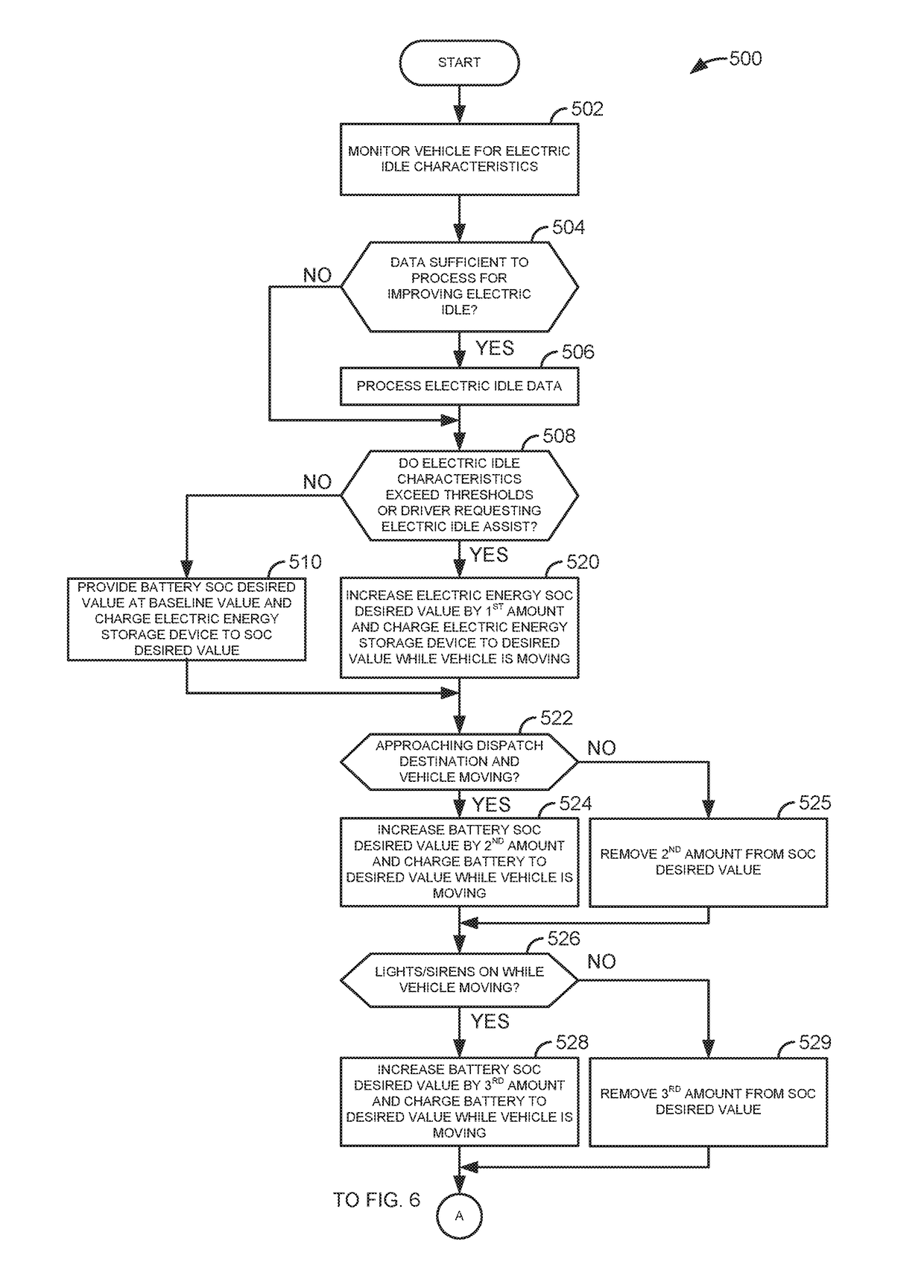
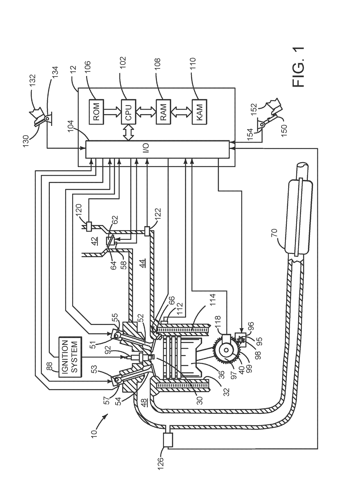
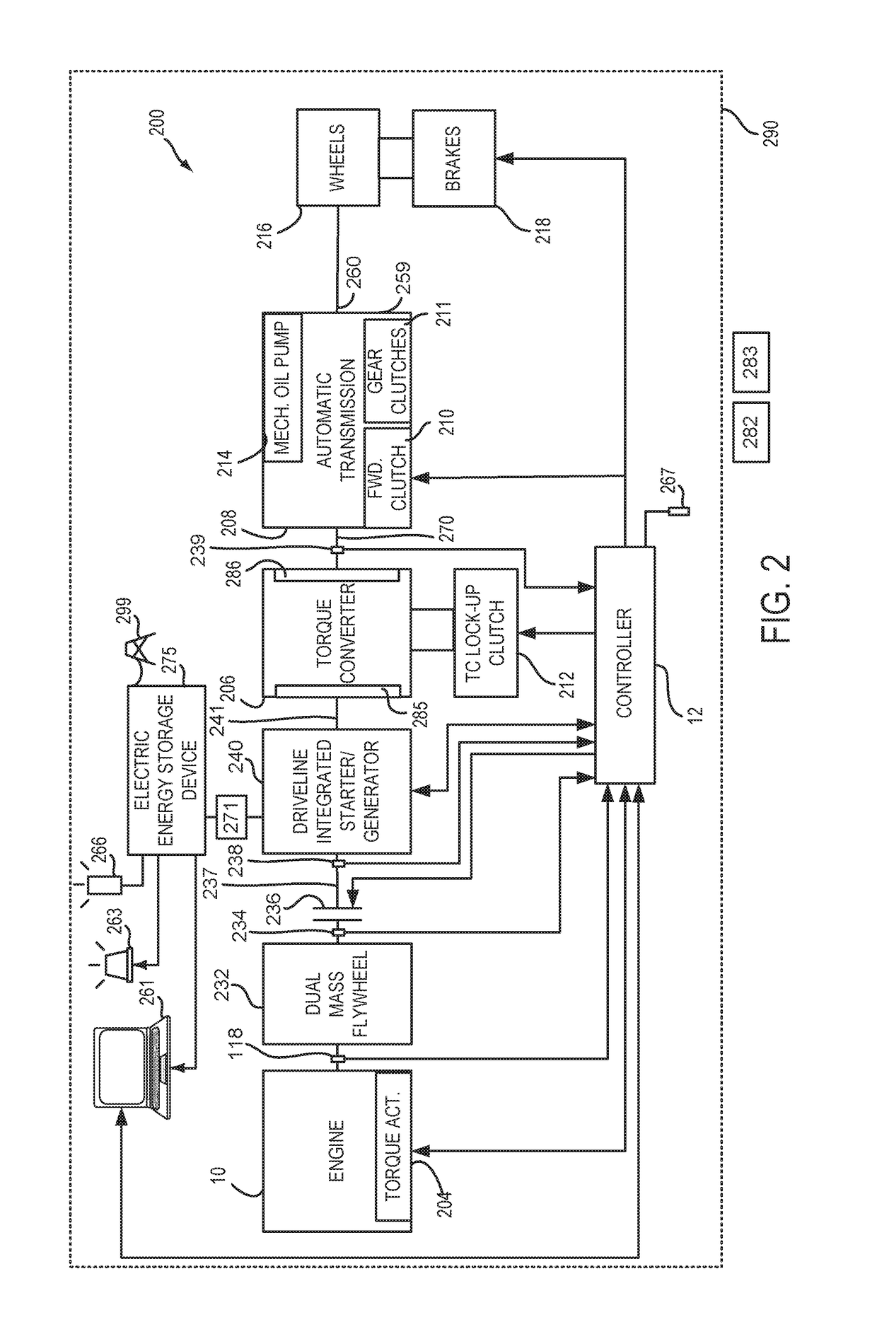
[0014]The present description is related to operating a vehicle in an electric idle mode and adjusting battery state of charge to extend the electric idle mode so as to reduce a number of engine starts that may result from operating the vehicle in the electric idle mode. The vehicle may include a hybrid vehicle driveline as shown in FIGS. 1-3. The vehicle may operate according to the vehicle operating sequence shown in FIG. 4. A method for adjusting operating the vehicle according to the sequence of FIG. 4 is shown in FIGS. 5 and 6.

[0015]Referring to FIG. 1, internal combustion engine 10, comprising a plurality of cylinders, one cylinder of which is shown in FIG. 1, is controlled by electronic engine controller 12. Engine 10 includes combustion chamber 30 and cylinder walls 32 with piston 36 positioned therein and connected to crankshaft 40. Flywheel 97 and ring gear 99 are coupled to crankshaft 40. Starter 96 includes pinion shaft 98 and pinion gear 95. Pinion shaft 98 may selectiv...


PUM


Abstract

Systems and methods for operating a vehicle in an electric idle mode are presented. The vehicle electrical idle mode may be characterized as a mode where the vehicle's engine is off; the vehicle increases torque to vehicle wheels responsive to an application of an accelerator pedal, release of a brake pedal, or a vehicle occupant shifting a transmission; and the vehicle's battery supplies electrical energy to devices of the vehicle being operated by a vehicle occupant.

Description

FIELD[0001]The present description relates to systems and methods for extending a period of time a vehicle may provide electrical energy to devices while an energy storage device of the vehicle is not receiving charge. The methods and systems may be useful for a variety of hybrid and electrically powered drivelines.BACKGROUND AND SUMMARY[0002]Hybrid vehicles may be used as emergency vehicles such as police interceptors or fire department command and control vehicles. While performing these duties, the vehicles may spend large amounts of time in a stationary state while police officers or firemen perform paperwork or receive information from a dispatch service or other police officers or firemen. The vehicle's engine may be stopped while the vehicle is stopped to conserve chemical fuel (e.g., gasoline). The vehicle's energy storage device may supply electrical energy to electrical consumers such as radios, computer systems, lights, sirens, etc. Such operating conditions may be referr...

Claims


Application Information

Patent Timeline
Patent Type & Authority Patents(United States)
IPC IPC(8): B60L11/18B60W10/06B60W10/26
CPCB60L11/1861B60W10/26B60W10/06B60W10/08B60W20/10B60W30/18054B60W2510/0638B60W2510/244B60W2520/10B60W2710/083B60W2710/0666B60K6/445B60W50/0097B60K2006/4825B60W2510/0657B60W2510/083B60W2510/305B60W2710/244B60W2710/248B60W20/11B60L2240/44B60L2240/12B60L2240/42B60L2240/80B60L2260/50B60L50/61B60L50/62B60L58/12B60W2540/215Y02T10/62Y02T10/64Y02T10/70Y02T10/7072
Inventor MILLER, KENNETH JAMESPORRAS, ANGEL FERNANDOPERKINS, WILLIAM PAULKAPADIA, JIMMY
Owner FORD GLOBAL TECH LLC
Learn More