
Sludge Reduction System for Wastewater Treatment

a wastewater treatment and wastewater technology, applied in the nature of treatment water, sludge treatment by oxidation, separation processes, etc., can solve the problems of limited pumping overboard into the sea, frequent maintenance of dewatering equipment, and significant maintenance of holding tank and discharge pumps, etc., to achieve lower biosolids, increase solids concentration, and high viscosity

Inactive Publication Date: 2008-07-03
NAVALIS ENVIRONMENTAL SYST
View PDF2 Cites 1 Cited by
  • Summary
  • Abstract
  • Description
  • Claims
  • Application Information

AI Technical Summary

Benefits of technology

[0011]The invention is incorporated in a sludge reduction system (the “sludge reduction system”) that reduces the volume of solids contained in a fluid medium such as a wastewater stream. The system reduces the disposal burden and reduces odors by oxidizing organic material such as raw or activated sludge in an ozone oxidation zone and then separates the concentrated sludge for removal in a concentrated sludge extraction zone. Among other things, the sludge reduction system is particularly useful in applications such as cruise ships because (1) the reduction of sludge saves space and energy costs, and (2) the reduction of odors makes shipboard treatment by incineration and / or drying less objectionable for passengers than under current systems.
[0017]Another advantage of the sludge reduction system is that it enables the use of smaller sludge treatment equipment and handling systems.

Problems solved by technology

Pumping overboard into the sea is limited by local and international laws which may require the ship to alter course or plan in advance a course that will position it for discharging sludge.
Sludge holding tank may require aeration blowers and the holding tank and discharge pumps, valves and piping may require significant maintenance.
Dewatering equipment requires frequent maintenance and current methods produce objectionable odors during the process.
A great deal of energy is required to dry this material for incineration due to the low solids concentration.
A consequence of drying this material is production of objectionable odors that limit the operation of these type systems.
Dryers are large, heavy and require significant amounts of energy to operate.
They also require operator attention and routine maintenance.

Method used


Image

  • Sludge Reduction System for Wastewater Treatment
  • Sludge Reduction System for Wastewater Treatment
  • Sludge Reduction System for Wastewater Treatment

Examples


Embodiment Construction

[0026]The descriptions below are merely illustrative of the presently preferred embodiments of the invention and no limitations are intended to the detail of construction or design herein shown other than as defined in the appended claims.

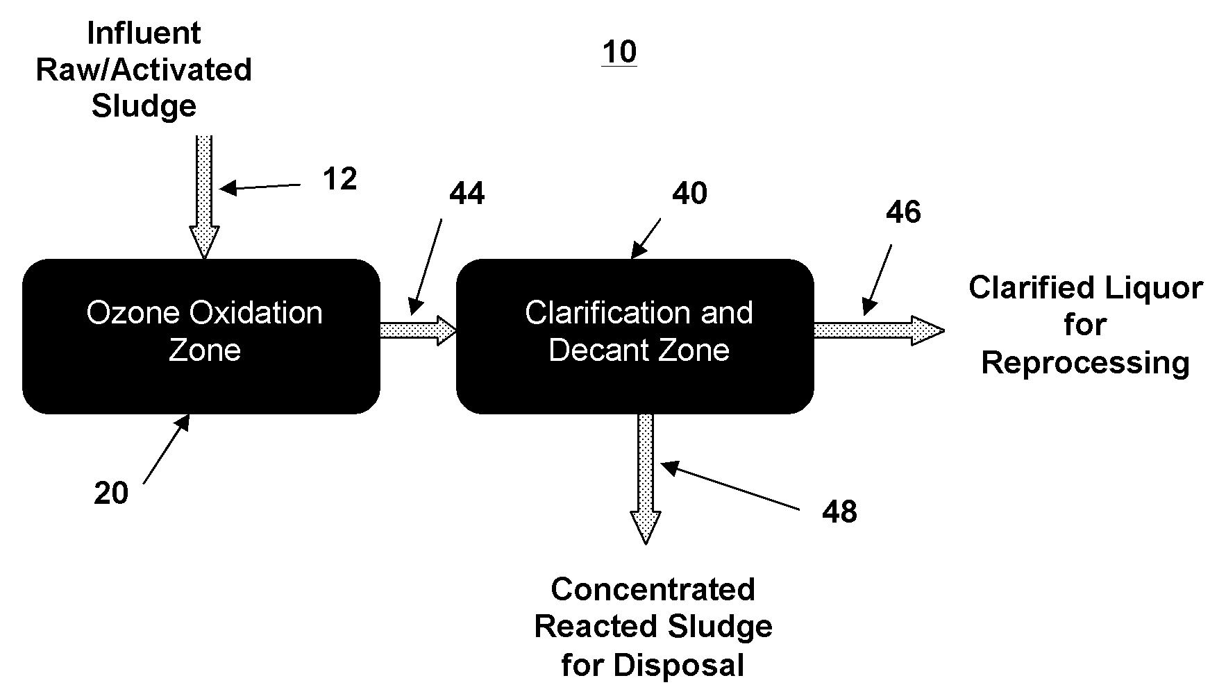
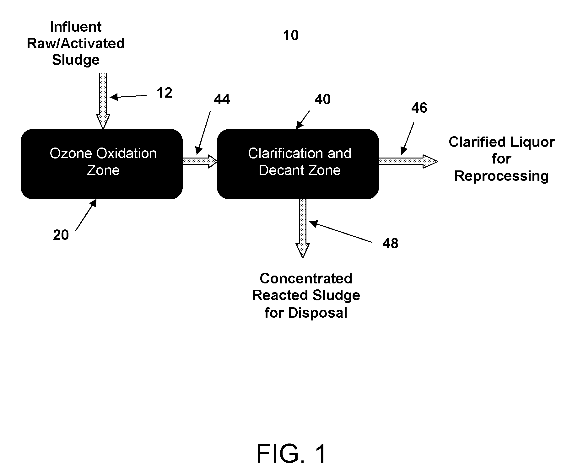
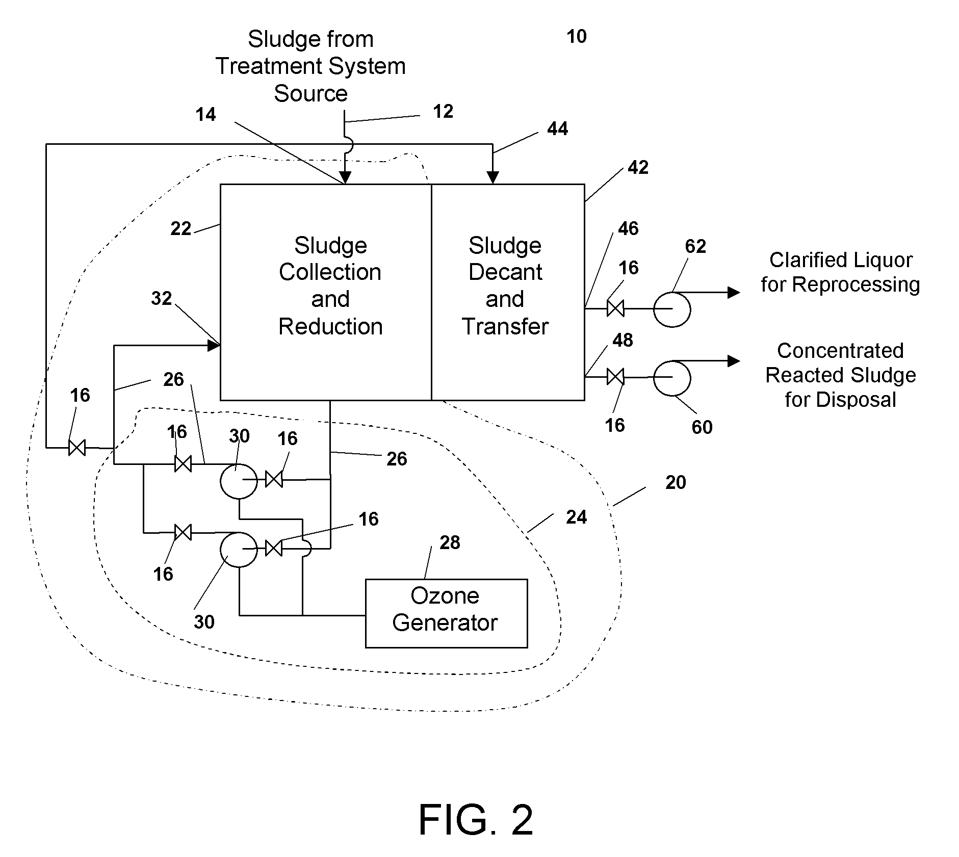
[0027]As shown in FIGS. 1 and 2, the sludge reduction system 10 relies on two principle zones: an ozone oxidation zone 20 and a concentrated sludge extraction zone 40. In the preferred embodiment, the ozone oxidation zone 20 comprises a first vessel 22 for holding sludge and an ozone infusing subsystem 24. The ozone infusing subsystem 24 preferably comprises a recirculation line 26, an ozone generator 28 and at least one ozone dissolving pump 30 for infusing ozone into the sludge in the first vessel 22. The first vessel 22 can be most any shape. The size of the first vessel 22 will depend on the volume of sludge to be treated. It is preferred that the first vessel 22 be constructed from 316L stainless steel.

[0028]In the preferred embodiment, the co...


PUM

PropertyMeasurementUnit
Volumeaaaaaaaaaa

Abstract

A sludge reduction system that reduces the volume of solids contained in a fluid medium such as a wastewater stream. The system reduces the disposal burden and reduces odors by oxidizing organic material such as raw or activated sludge in an ozone oxidation zone and then separating the concentrated sludge for extraction in a concentrated sludge extraction zone. The sludge reduction system is particularly useful in applications such as cruise ships because (1) the reduction of sludge saves space and energy costs, and (2) the reduction of odors permits shipboard treatment rather than holding in tanks for later discharge.

Description

BACKGROUND OF THE INVENTION[0001]1. Field of the Invention[0002]The present invention relates generally to wastewater treatment systems, and more particularly to improved sludge reduction for wastewater treatment systems.[0003]2. Discussion of the Related Art[0004]Many of today's wastewater treatment systems produce large volumes of sludge (raw, activated, and reacted) as a process byproduct. On a cruise ship, for example, this sludge is typically 1-5% solids by weight. Currently, this sludge is (1) pumped overboard into the sea, (2) further processed by dewatering (e.g., press or centrifuge) and / or drying for incineration, or (3) pumped to a shore receiving facility. These current methods of treating sludge have known disadvantages.[0005]Pumping overboard into the sea is limited by local and international laws which may require the ship to alter course or plan in advance a course that will position it for discharging sludge. Pumping overboard will require a holding tank of signific...

Claims


Application Information

Patent Timeline
IPC IPC(8): C02F1/78
CPCC02F1/78C02F2303/02C02F2103/008C02F11/06Y02W10/40
Inventor MCCREA, JACK L.MARKLE, STEPHEN P.JONES, RANDALL J.
Owner NAVALIS ENVIRONMENTAL SYST
Learn More