
Breast pump

a technology for pumping and breasts, applied in the field of breast pumps, can solve the problems of increased breast vacuum, increased discomfort for users, and/or exceeding the safe limit, and damage to the vacuum pump

Active Publication Date: 2015-08-27
KONINKLJIJKE PHILIPS NV
View PDF7 Cites 5 Cited by
  • Summary
  • Abstract
  • Description
  • Claims
  • Application Information

AI Technical Summary

Benefits of technology

The present invention relates to a breast pump with a membrane that separates the chamber into two spaces. The membrane is deformable in response to a reduction of pressure in the first space to generate pressure reduction in the second space. A limiter in the chamber restricts deformation of the membrane to prevent excessive pressure reduction in the second space. The membrane is in contact with a textured surface to minimize noise generated during the process. Patent text describes a new design featuring a deformable membrane and a limitation on its deformation to prevent unnecessary pressure reduction. The invention aims to provide a more effective and comfortable breast pump.

Problems solved by technology

However, one problem with the above arrangement is that if the valve fails to open then the vacuum acting on the user's breast continues to increase as the vacuum pump continues to reduce the pressure acting on the membrane.
Therefore, the vacuum acting on the user's breast may cause discomfort to a user and / or may exceed a safe limit.
Furthermore, the prolonged and increased vacuum can cause damage to the vacuum pump, and may prevent the user from removing their breast from the vacuum pump.
It is also known that movement of the diaphragm in the chamber can cause a noise, such as a loud squeak, to be generated.
This noise is typically caused by the flexible membrane coming into contact with, moving over, or moving away from contact with, the inner surface of the chamber.

Method used


Image

  • Breast pump
  • Breast pump
  • Breast pump

Examples


Embodiment Construction

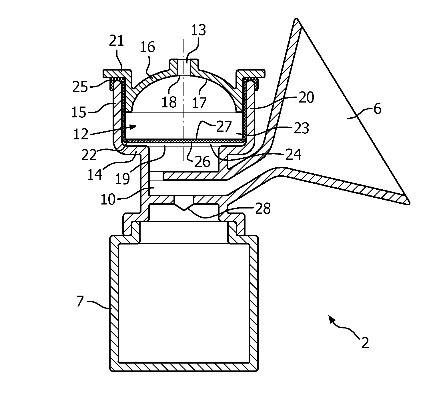
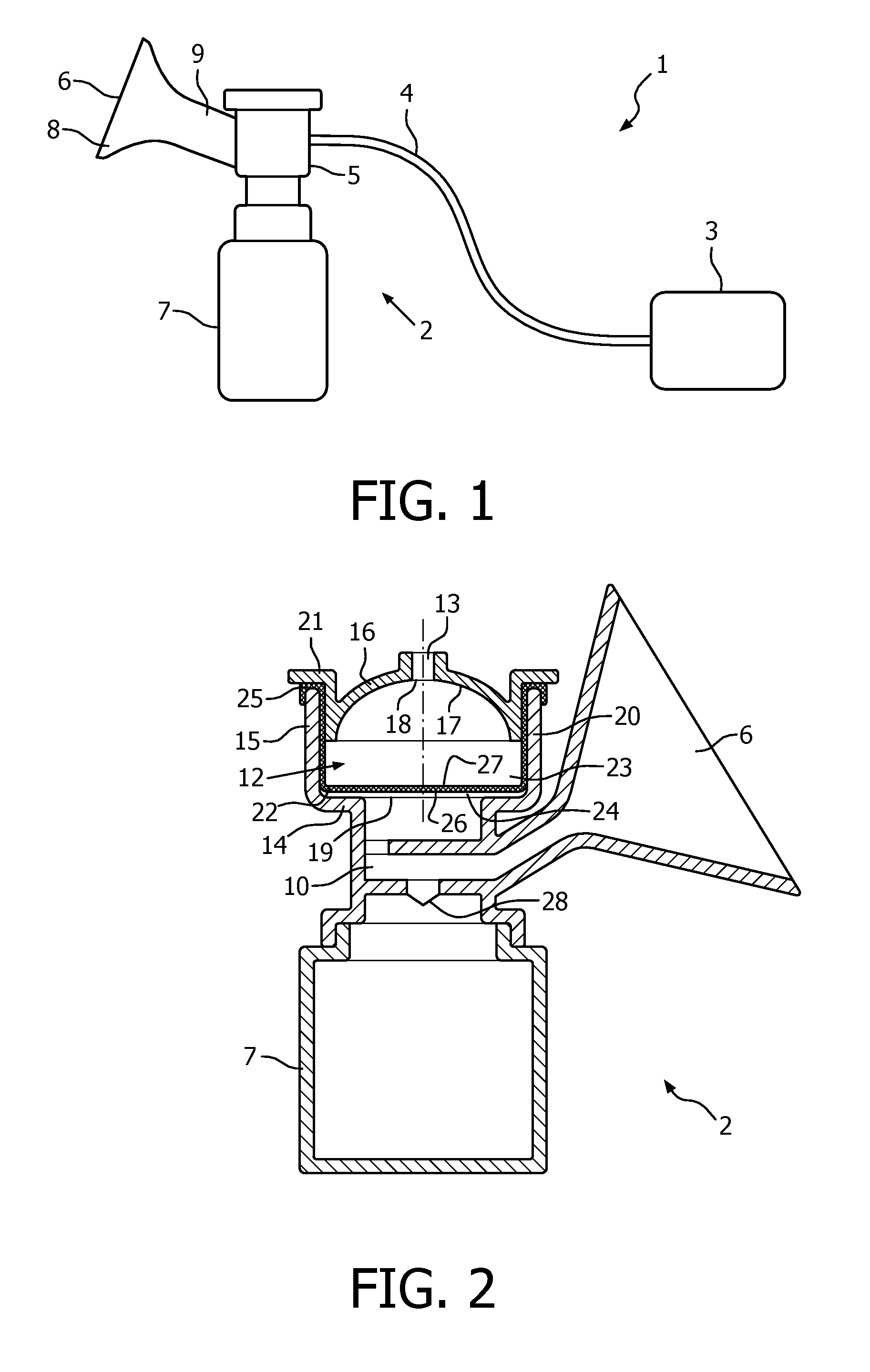
[0056]A breast pump system is shown in FIG. 1. The breast pump system 1 comprises a breast pump 2, also known as an expression unit, and an operating unit 3.

[0057]The breast pump 2 and the operating unit 3 are connected by a tube 4. The tube 4 provides a fluid communication between the breast pump 2 and the operating unit 3. The tube 4 may also be used to provide an electrical connection between the breast pump 2 and the operating unit 3. For example, the tube may supply an operating signal or electrical power between the breast pump and the operating unit.

[0058]The breast pump 2 has a main body 5, a funnel 6 and a collection vessel 7. The collection vessel 7, or receptacle, collects milk expressed from a user's breast and may take the form of a feeding bottle or bag. The collection vessel 7 is attached to the main body 5 by a screw fitting, although it will be understood that alternative releasable attachment means may be used, such as clips (not shown).

[0059]The breast-receiving f...


PUM


Abstract

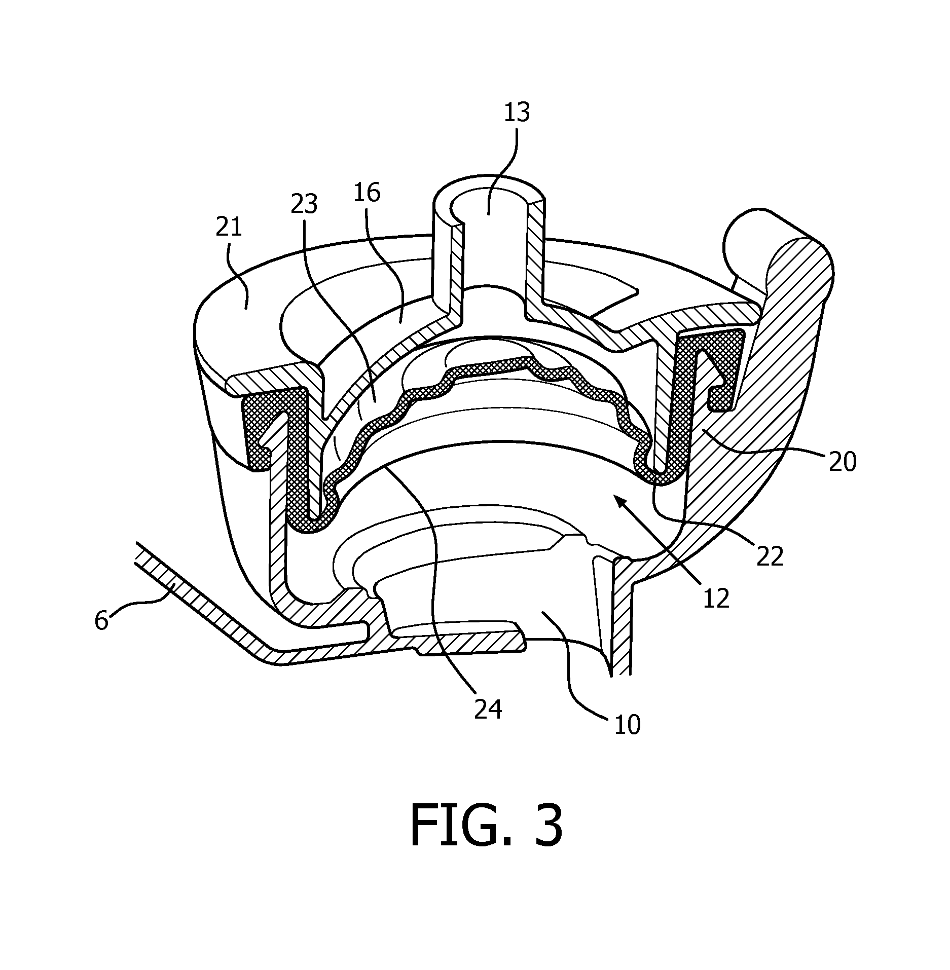
The present application relates to a breast pump. The breast pump has a chamber (12) and a membrane (22). The membrane (22) is receivable in the chamber (12) to separate the chamber (12) into first and second spaces (23, 24). The membrane (22) is also deformable in the chamber in response to a reduction of pressure in the first space (23) to cause a reduction of pressure in the second space (24). A limiter (16) is in the chamber (12) against which the membrane (22) is locatable to limit deformation of the membrane (22).

Description

FIELD OF THE INVENTION[0001]The present invention relates to a breast pump. The present invention also relates to a breast pump system.BACKGROUND OF THE INVENTION[0002]Breast pumps are well known devices for extracting milk from a breast of a user. A breast pump may be used if the baby or infant is not itself able to express milk from the breast, or if the mother is separated from the baby or infant, for example, if away from the baby at work. The use of a breast pump to express milk may also be used to stimulate and increase milk production in women with a low milk supply.[0003]Breast pumps make use of a vacuum to induce milk expression from a nursing mother's breast. The pumping action of the device draws the milk from the nipple to a collection vessel, and the pressure and / or frequency may be adjustable to the preferences of the mother.[0004]A breast pump system generally comprises a breast pump, acting as an expression unit, and an operating unit to operate the breast pump. The ...

Claims


Application Information

Patent Timeline
Patent Type & Authority Applications(United States)
IPC IPC(8): A61M1/06A61M1/00
CPCA61M1/06A61M1/0072A61M2210/1007A61M1/82
Inventor AALDERS, ARNOLDBIJLOO, MICHIEL DIRK AUGUSTINUS
Owner KONINKLJIJKE PHILIPS NV
Learn More