Panel jig device for vehicle

a technology for jig devices and vehicles, which is applied in the direction of metal-working machine components, manufacturing tools, transportation and packaging, etc., can solve the problems of limited use of panels of various kinds of vehicles, increased investment costs, and difficulty in trunk leads and tail gates

Active Publication Date: 2016-04-05
HYUNDAI MOTOR CO LTD
View PDF3 Cites 0 Cited by
  • Summary
  • Abstract
  • Description
  • Claims
  • Application Information

AI Technical Summary

Benefits of technology

[0012]The present invention has been made in an effort to provide a panel jig device for a vehicle having advantages of being able to adjust an angle to fit to the shape of a panel restriction surface so that it can restrict (e.g., clamp) various panels for various models, types, or kinds of vehicles.

Problems solved by technology

However, common panel jig devices have problems in that they can be difficult to use for trunk leads and tail gates having various shapes and sizes for the kinds of vehicles.
When different exclusive jig devices are used for the kinds of vehicles and the items, as described above, additional cost for reconstructing the jig devices or manufacturing a new jig device is required for a new kind of vehicle, such that the entire investment cost may be increased.
The clamp units may be exclusive units of which the locator surface and the clamping angle (clamping operation angle) are adjusted in accordance with the restriction surface of panels, but it is disadvantageous for various kinds of vehicles because the shape of the panel restriction surfaces are various for the kinds of vehicles.
However, the swivel clamp unit can adjust the swivel angle of the clamping angle only within about ±15, such that it has a limitation in use for the panels of various kinds of vehicles.
Further, when there is a difference between the clamping angle and the angle of the panel restriction surface (holding portion of a panel), the panel restriction surface (holding surface of a panel) may be damaged by the clamping angle in clamping.

Method used


Image

  • Panel jig device for vehicle
  • Panel jig device for vehicle
  • Panel jig device for vehicle

Examples


Embodiment Construction

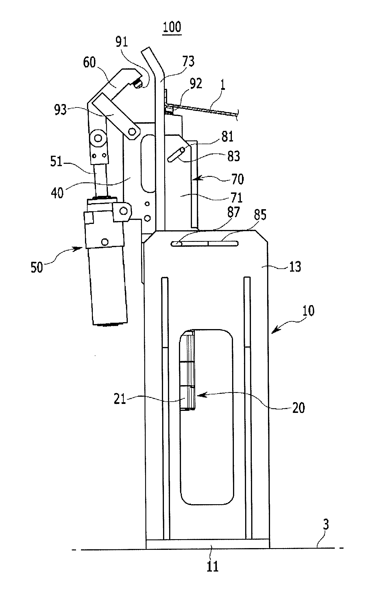
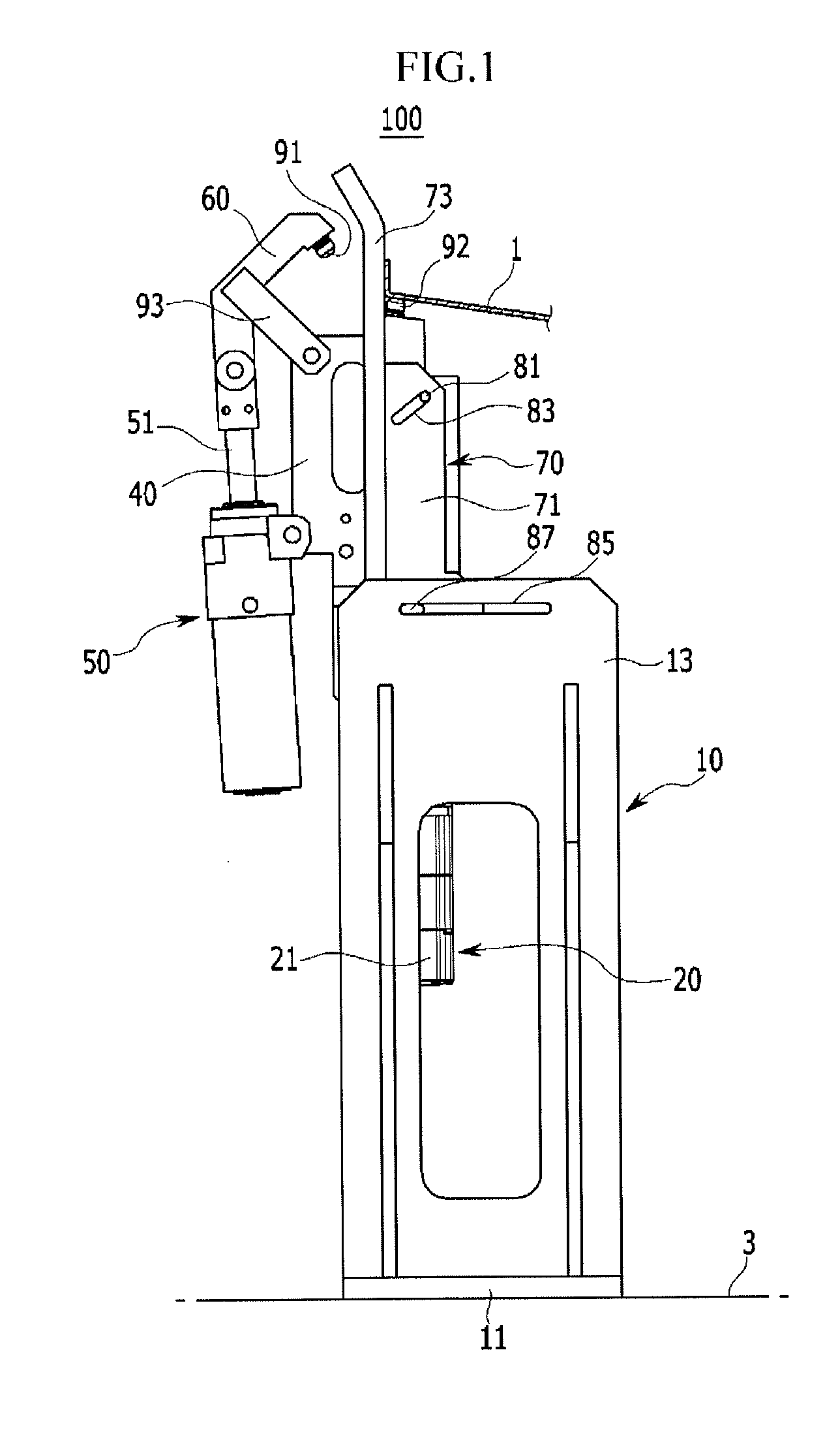
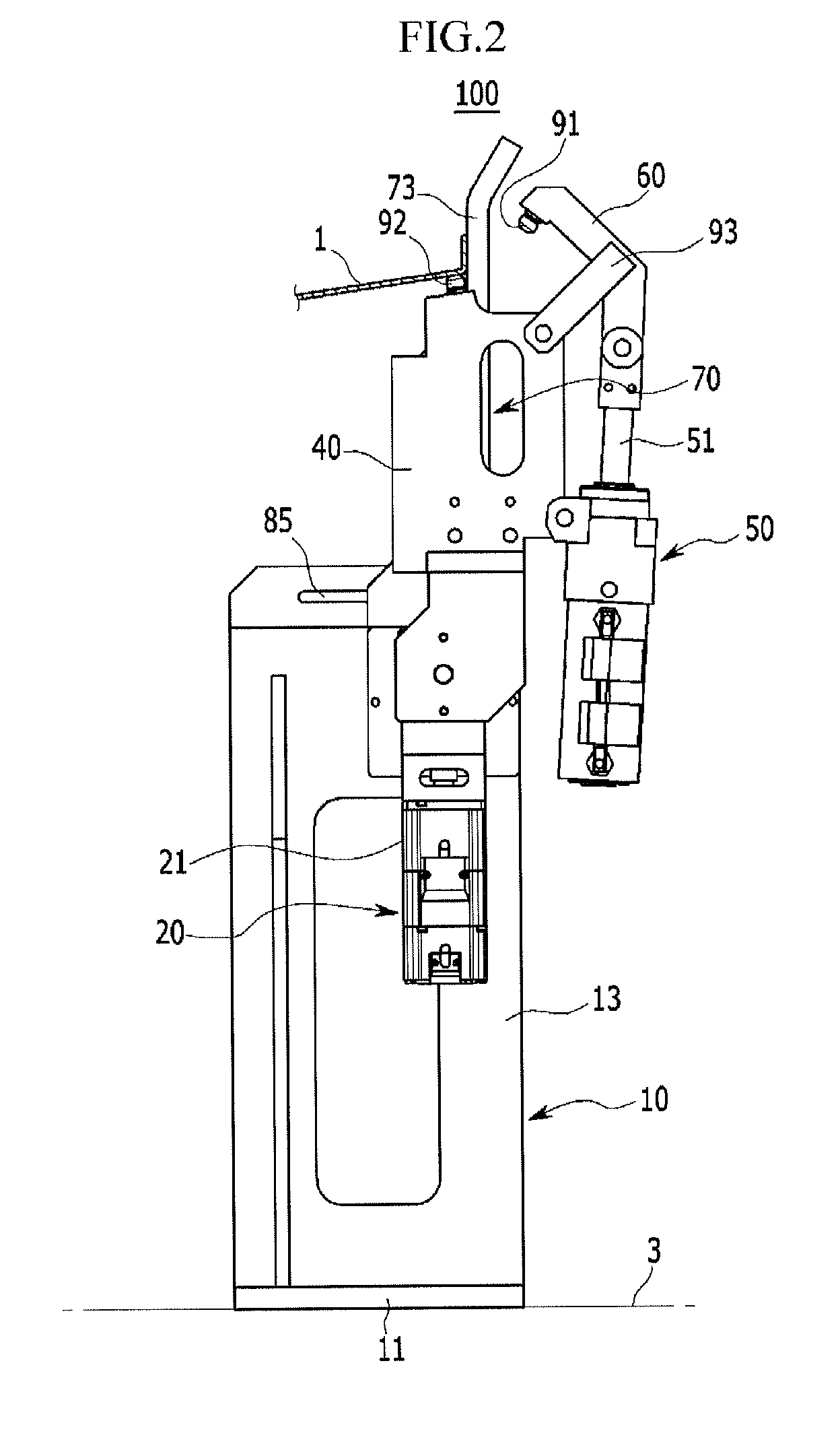
[0026]Reference will now be made in detail to various embodiments of the present invention(s), examples of which are illustrated in the accompanying drawings and described below. While the invention(s) will be described in conjunction with exemplary embodiments, it will be understood that present description is not intended to limit the invention(s) to those exemplary embodiments. On the contrary, the invention(s) is / are intended to cover not only the exemplary embodiments, but also various alternatives, modifications, equivalents and other embodiments, which may be included within the spirit and scope of the invention as defined by the appended claims.

[0027]The unrelated parts to the description of the exemplary embodiments are not shown to make the description clear and like reference numerals designate like element throughout the specification. Further, the sizes and thicknesses of the configurations shown in the drawings are provided selectively for the convenience of descriptio...


PUM


Abstract

A panel jig device for a vehicle may include: a base bracket disposed on a jig base; a motor assembly mounted on the base bracket and including a rotary shaft; a locator having a locator end supporting a holding portion of a panel, connected to the rotary shaft of the motor assembly, and rotating about the rotary shaft with rotation of the rotary shaft; a clamping cylinder including an operating rod selectively operating forward / backward, and hinged to the locator; and a damper having one end hinged to the operating rod, a center portion hinged to the locator, and the other end with a clamping end supporting the holding portion of the panel.

Description

CROSS-REFERENCE TO RELATED APPLICATION[0001]The present application claims priority of Korean Patent Application Number 10-2013-0051379 filed on May 7, 2013, the entire contents of which application are incorporated herein for all purposes by this reference.BACKGROUND OF INVENTION[0002]1. Field of Invention[0003]The present invention relates to a panel jig device for a vehicle. More particularly, the present invention relates to a panel jig device for a vehicle which can adjust a clamping angle in correspondence to a panel restriction surface (a holding portion of a panel) which varies depending on the models, types or kinds of vehicles.[0004]2. Description of Related Art[0005]In general, vehicle bodies are formed in a body in white through a process of assembling various product panels produced through sub-processes for the vehicle bodies. The vehicle bodies as described can be assembled through the processes of mounting various panel parts such as a floor panel, side panels, a roo...

Claims


Application Information

Patent Timeline
Patent Type & Authority Patents(United States)
IPC IPC(8): B23Q3/18B23P19/04B23Q1/26B25B5/00
CPCB23Q1/26B23P19/04B25B5/006B62D65/04B62D65/02B62D65/00
Inventor JANG, YOON
Owner HYUNDAI MOTOR CO LTD
Why Eureka
Try Eureka