Fishing rod holder

a technology for fishing rods and holders, applied in fishing, other angling devices, applications, etc., can solve the problems of cumbersome fishing rod holders, knob wear and frequently breaks, and prior art rod holders are difficult to manipulate, etc., to achieve convenient adjustment and economic manufacturing

Inactive Publication Date: 2006-10-03
MILLER JEFFREY
View PDF23 Cites 29 Cited by
  • Summary
  • Abstract
  • Description
  • Claims
  • Application Information

AI Technical Summary

Benefits of technology

[0007]It is an object of the present invention to provide a fishing rod holder for mounting to a boat that is easy to adjust and economic to manufacture.
[0009]A more specific object of the present invention is to provide a fishing rod holder wherein the angle of the rod holder can be adjusted without turning a set screw or using separate tools.
[0010]A more specific object of the present invention is to provide a fishing rod holder wherein the position of the rod can be adjusted by depressing a spring activated button on the side of the rod holder.
[0011]A further object of the present invention is to provide a fishing rod holder that once adjusted to the desired angle by the user, it can be locked in position by simply releasing the button.

Problems solved by technology

To the extent that there are a variety of adjustable fishing rod holders previously taught, the known prior art rod holders are difficult to manipulate and often times require tools to adjust their positions.
One such type of cumbersome fishing rod holder requires a set screw for adjusting the preferred angle.
Other prior art uses a screw with a knob that can be turned by hand but often, with continued use, the knob wears and frequently breaks.

Method used


Image

  • Fishing rod holder
  • Fishing rod holder
  • Fishing rod holder

Examples


Embodiment Construction

[0021]The following description of the preferred embodiment(s) is merely exemplary in nature and is in no way intended to limit the invention, its application, or uses.

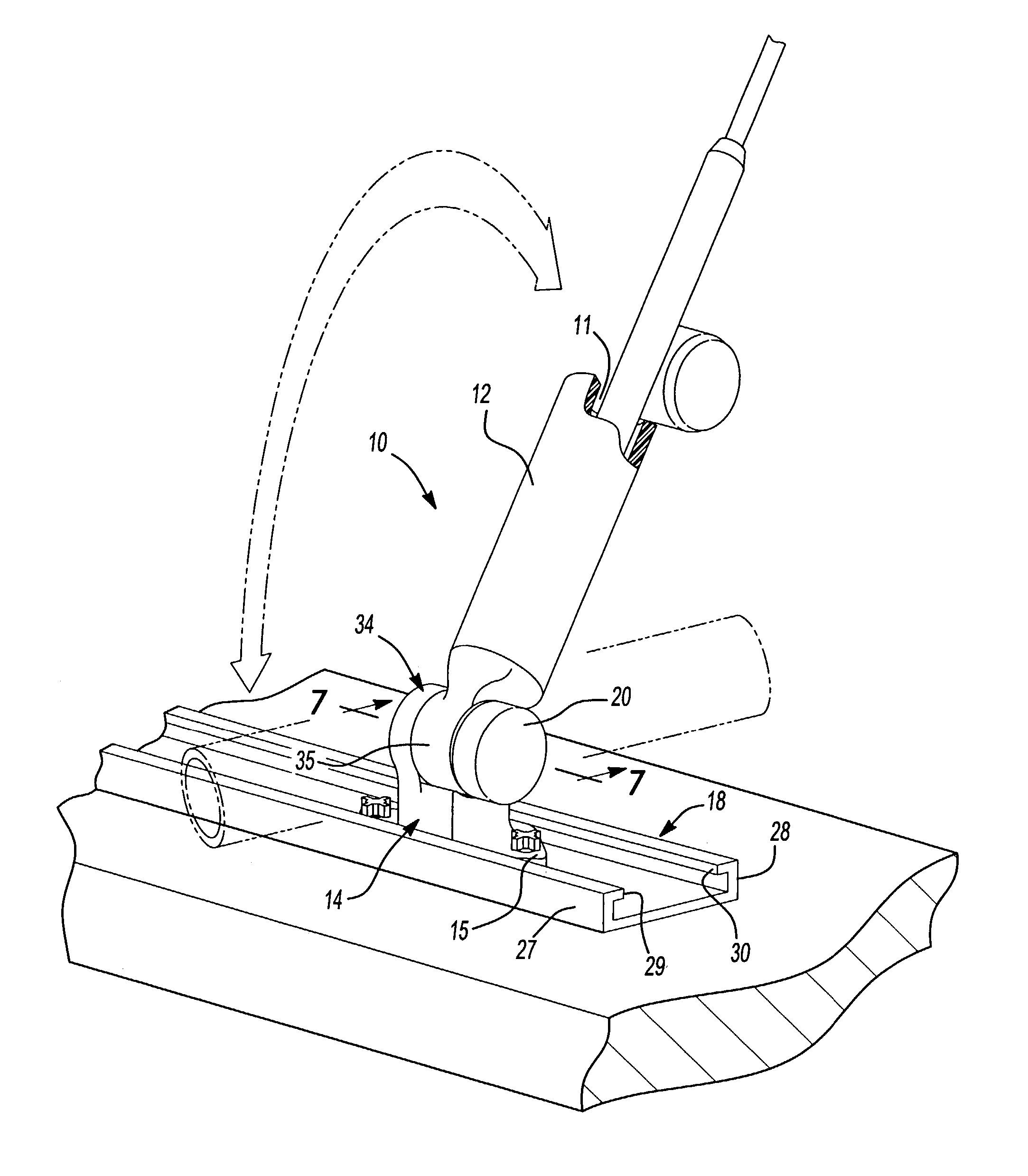
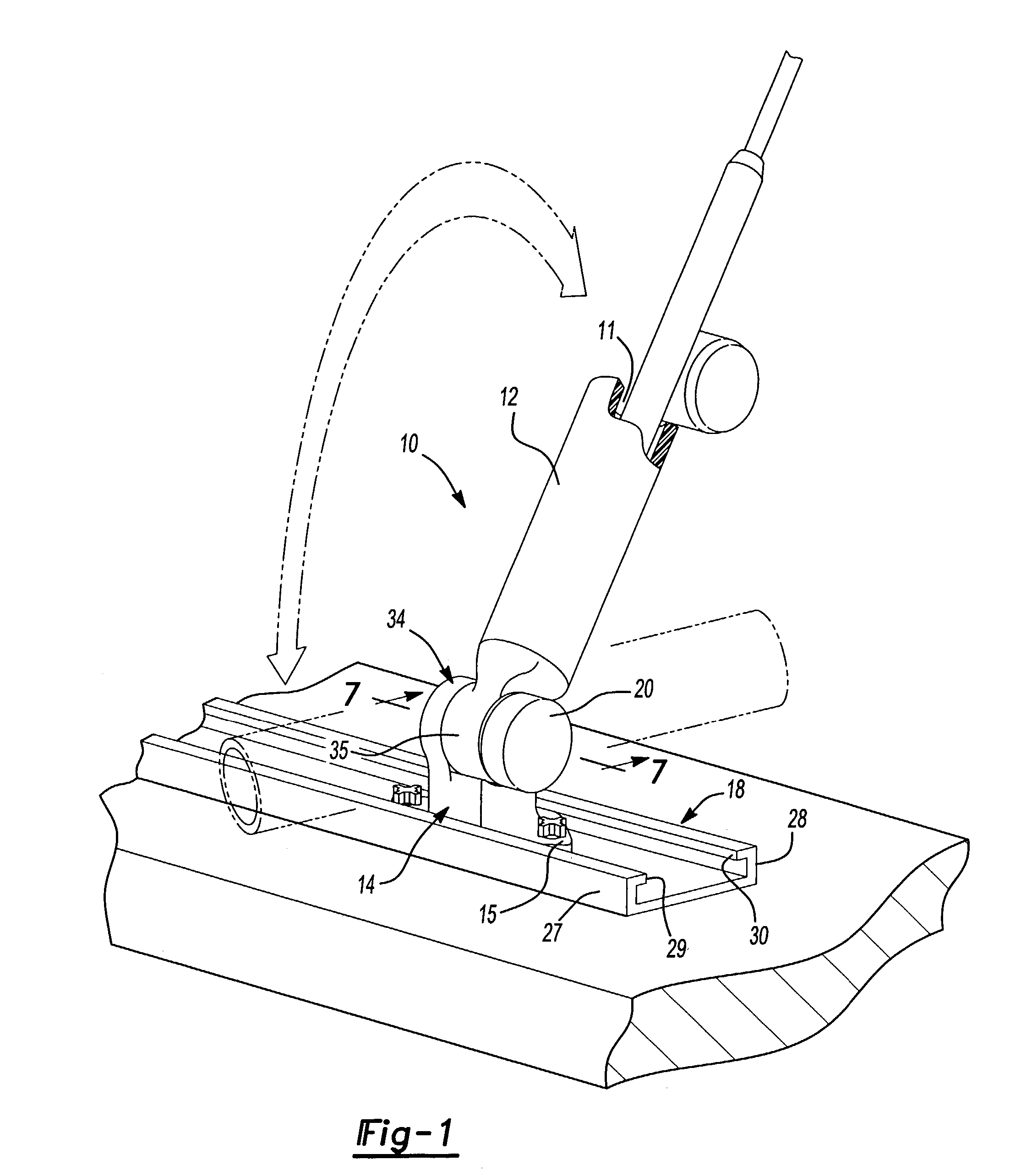
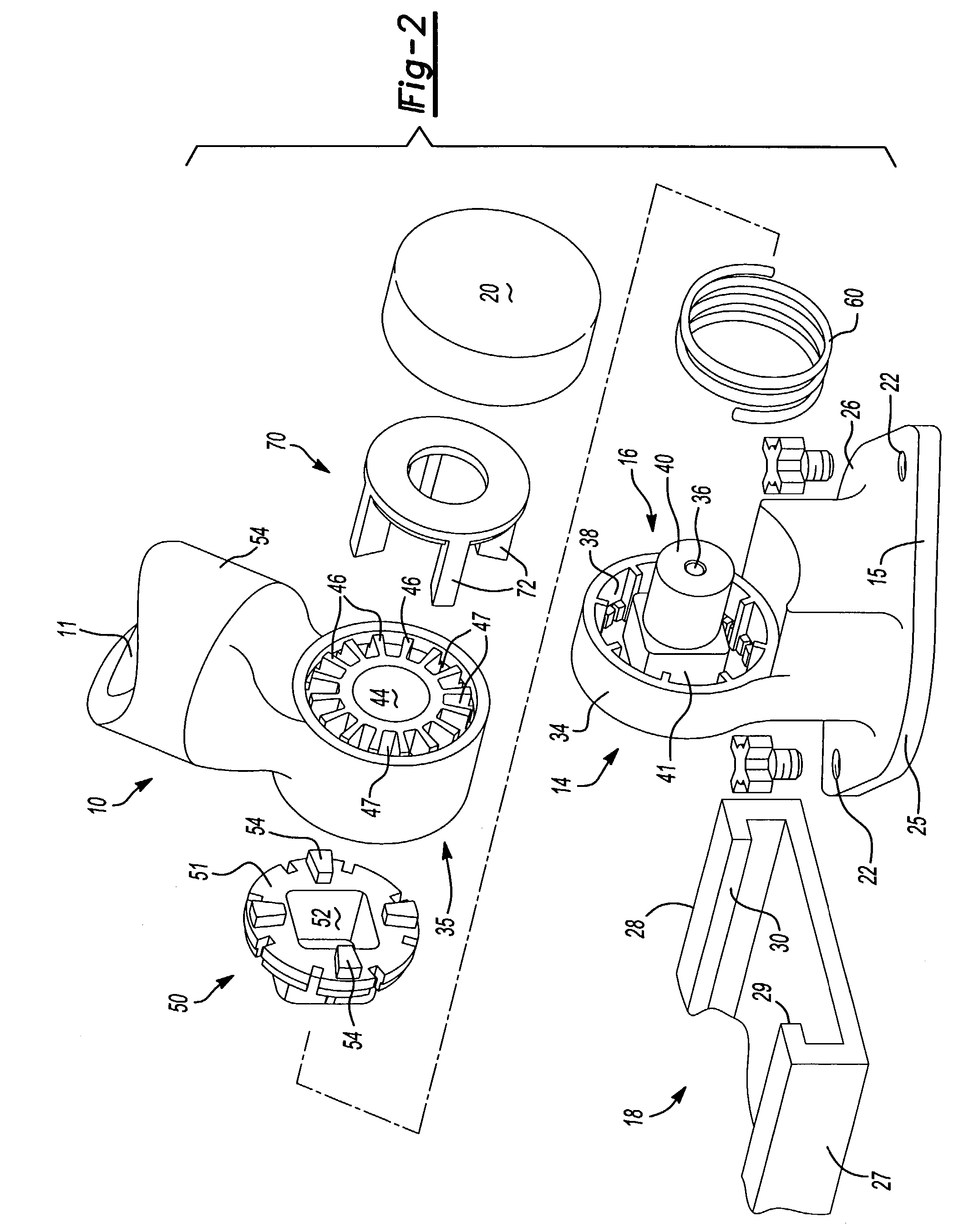
[0022]The improved fishing rod holder 10 is comprised of a fishing rod holding tube 12, a mounting base 14, and a pivot and locking mechanism 16 for adjusting the desired angle of the rod holder 10. The angle of the rod holder can be adjusted through an entire one hundred eighty degree range as desired by the user. The handle of the fishing rod is received within bore 11 of the holding tube 12. The mounting base 14 includes a plate lower portion 15 with integral sides 25 and 26 that are received in a channel member 18. The channel member is of a general C-shape in cross section and has integral first and second sides 27 and 28, and integral first and second flanges 29 and 30 beneath which sides 25 and 26 of the plate lower portion 15 are received. The channel member can be affixed to a variety of surfaces such as the ...


PUM


Abstract

A fishing rod holding apparatus that can be mounted alone or in series to a vessel such as a boat, wherein the assembly includes a mounting base, a channel for receiving and attaching one or more fishing rod holding assemblies. Each rod-holding assembly comprises a fishing rod holding tube and a spring biased pivoting assembly. The pivoting assembly allows the angle of the fishing rod holder to be adjusted manually by depressing a button while simultaneously repositioning the rod holder. Once the desired angle is achieved, the assembly locks in position by simply releasing the button.

Description

CROSS-REFERENCE TO RELATED APPLICATIONS[0001]This application claims the priority of U.S. Provisional Application No. 60 / 329,954, filed Oct. 17, 2001.FIELD OF THE INVENTION[0002]The present invention relates to a fishing rod holder. More specifically, the present invention relates to a boat mounted fishing rod holder that is manually adjustable to obtain a variety of rod angles and positions.BACKGROUND OF THE INVENTION[0003]There are many variations of fishing rod holders known in the art. These holders are generally used to hold a fishing rod and reel in a position allowing the fishing rod to be used without the need for the angler to hold it. Very often these holders are mounted to or near the stern of a boat for use during trolling operations. Additionally, anglers often do not care to hold the rod in their hands while fishing, even if the boat is not in motion, thereby allowing them to perform other tasks.[0004]Several fishing rod holders have been developed that allow for the m...

Claims


Application Information

Patent Timeline
Patent Type & Authority Patents(United States)
IPC IPC(8): A01K97/10
CPCA01K97/10
Inventor MILLER, JEFFREY
Owner MILLER JEFFREY
Why Eureka
Try Eureka