Method for reducing interference in transmitter and transmitter

Inactive Publication Date: 2005-11-29
NOKIA TECHNOLOGLES OY
View PDF17 Cites 6 Cited by
  • Summary
  • Abstract
  • Description
  • Claims
  • Application Information

AI Technical Summary

Benefits of technology

[0010]An advantage of the invention is that the noise level of the output signal of the linearized transmitter is on average lower than in prior-art transmitters. This is a result from the fact that in the transmitter according to the invention it is made certain that the levels of the modulator input signals stay above the noise level to a sufficient extent. Another advantage of the invention is that for the reason mentioned above it is possible to use a cheaper and, from the point of view of manufacturing, easier mod

Problems solved by technology

The latter results in various extra spurious spectra which may be located in bands corresponding to the other frequency division channels.
So, in this respect the power amplifier in a transmitter may prove to be a problematic component.
The drawback of the structure is that

Method used


Image

  • Method for reducing interference in transmitter and transmitter
  • Method for reducing interference in transmitter and transmitter
  • Method for reducing interference in transmitter and transmitter

Examples


Embodiment Construction

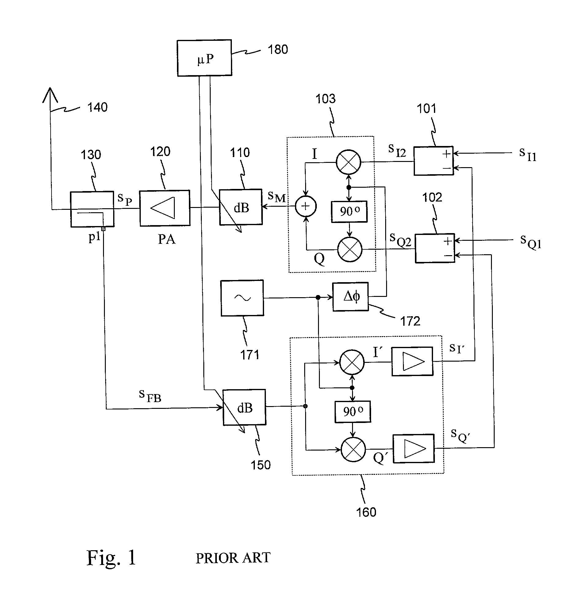
[0016]FIG. 1 was already discussed in connection with the description of the prior art.

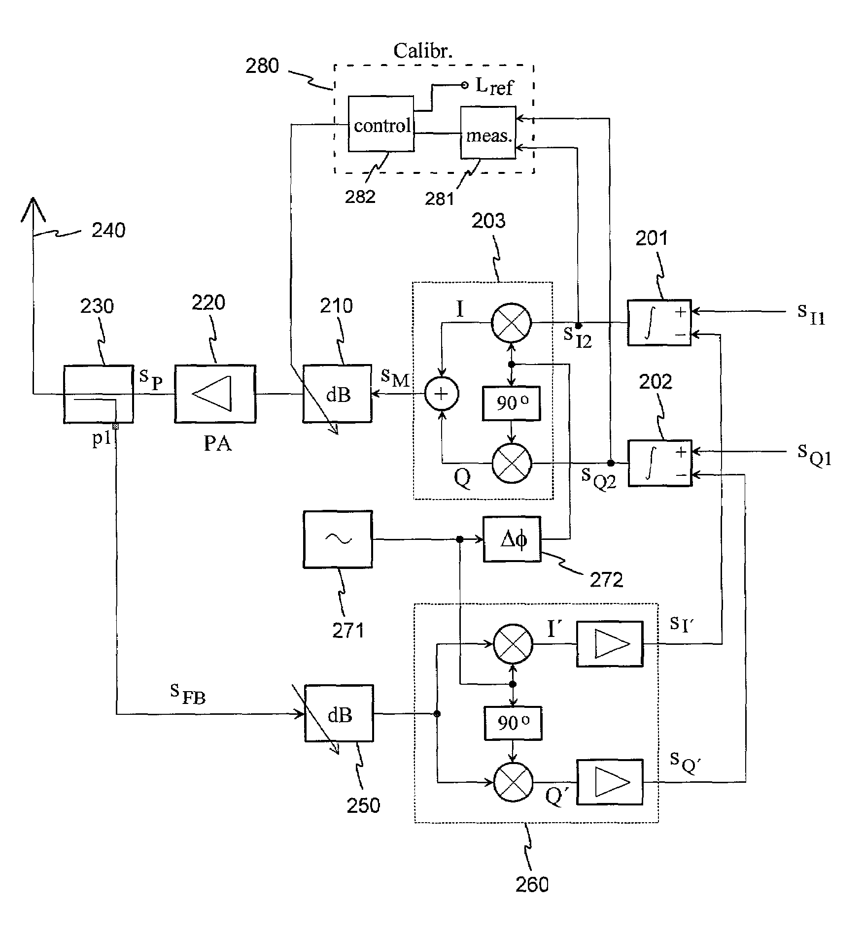
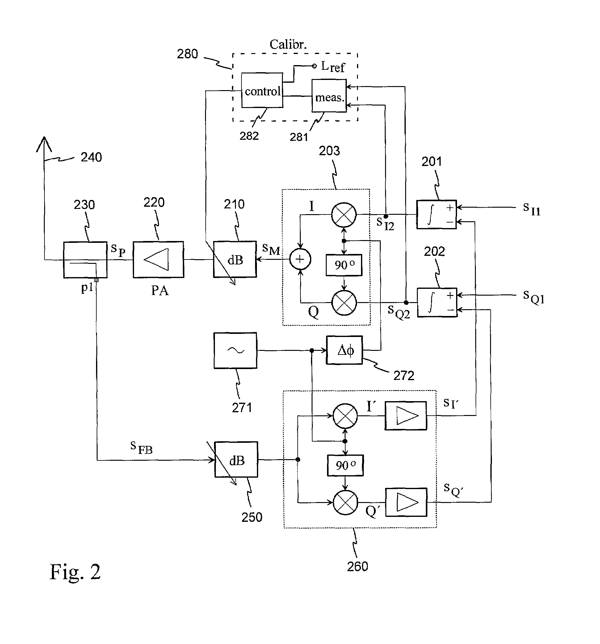
[0017]FIG. 2 shows a basic Cartesian loop like the one shown in FIG. 1. The differential amplifiers 201 and 202 in the transmitter input are shown to be integrators, which means that they amplify an integrated difference signal. Integration produces suitable slowness for the loop function in order to improve stability. A significant difference from the arrangement depicted in FIG. 1 is that the control information for the first level control unit 210 is taken from within the loop and not from outside the loop. In the arrangement according to FIG. 2, the levels of the output signals of the differential amplifiers 201, i.e. the input signals of the modulator 203, or at least one of them, is monitored by a measuring circuit 281 belonging to a calibrating unit 280. The output of the said measuring circuit is connected to a first input of a control circuit 282. At the second input of the control circui...


PUM


Abstract

The invention relates to a method for reducing interference in radio transmitters with feedback from the antenna end to the baseband side and to a transmitter applying the said method. In a Cartesian loop formed for the linearization of a transmitter, the levels of baseband input signals (sI2, sQ2) to a modulator are measured and the attenuation of a level control unit (210) following the modulator (203) is adjusted until the modulator input signal levels are sufficiently above the noise level. The adjustment may be carried out as a one-time procedure during the manufacturing process or repeatedly during the operation of the device. By means of the invention, the noise level of the output signal of a linearized transmitter can be made lower than in known transmitters. Moreover, the transmitter may utilize a cheaper and, from the point of view of manufacturing, easier 4modulator than known transmitters.

Description

BACKGROUND OF THE INVENTION[0001]The invention relates to a method for reducing interference in radio transmitters, which have feedback from the antenna end to the baseband side. The invention further relates to a transmitter applying the said method.[0002]In all radio systems utilizing multiple carrier wave frequencies it is important that the signals in the different frequency division channels not interfere with each other. Non-interference requires that transmission power levels are kept low enough and the spectrum of the transmission signal is confined as accurately as possible to the frequency band allocated to it. Spreading of the spectrum is caused by the modulation required by radio transmission and in particular by nonlinearity in the transmitter units. The latter results in various extra spurious spectra which may be located in bands corresponding to the other frequency division channels. In practice, there is always some nonlinearity in mixers and amplifiers, in principl...

Claims


Application Information

Patent Timeline
IPC IPC(8): H03F3/19H03F3/343
CPCH03F3/19H03F3/343
Inventor HAAPAKOSKI, ARTO
Owner NOKIA TECHNOLOGLES OY
Why Eureka
Try Eureka