System and method for frequency multiplexing in double-conversion receivers

a frequency conversion and receiver technology, applied in the field of frequency conversion receivers, can solve the problems of high insertion loss, poor signal-to-noise ratio, restricted wideband frequency conversion of signals, etc., and achieve the effect of reducing inter-modulation distortion, optimum signal-to-noise ratio, and saving power

Active Publication Date: 2010-11-09
SKYWORKS SOLUTIONS INC
View PDF13 Cites 11 Cited by
  • Summary
  • Abstract
  • Description
  • Claims
  • Application Information

AI Technical Summary

Benefits of technology

[0012]The use of multiple narrowband low insertion loss filters in each frequency segment allows the transmission of a large number of channels with optimum signal-to-noise ratio and having multiple down-conversion paths reduces the inter-modulation distortion. Wideband frequency conversion is achieved by placing multiple narrow bandwidth filters in parallel or dividing the IF band into one or more frequency segments. Further, the frequency-conversion receiver architecture of the present invention provides rejection of unwanted signals. The frequency-conversion receiver architecture of the present invention also allows the use of either high performance or low performance-analog-to-digital converters in IF signal detection. Moreover, the control switch of the frequency-conversion receiver architecture also helps in saving power by switching the frequency segments not in use to an ‘off’ state. Moreover, the wideband filter, which includes multiple narrowband filters, made on a single substrate, helps in minimizing process and temperature variations.

Problems solved by technology

However, the available IF filters have low bandwidth, which restricts the frequency conversion of wideband IF signals.
To process wideband IF signals wide-bandwidth filters are needed, which have high insertion loss.
High insertion loss filters cause poor signal-to-noise ratio, which limits the lower end of receiver dynamic range.
Further, the processing of wideband signals cause high inter-modulation distortion, which sets the limit on the high end of receiver dynamic range.

Method used


Image

  • System and method for frequency multiplexing in double-conversion receivers
  • System and method for frequency multiplexing in double-conversion receivers
  • System and method for frequency multiplexing in double-conversion receivers

Examples


Embodiment Construction

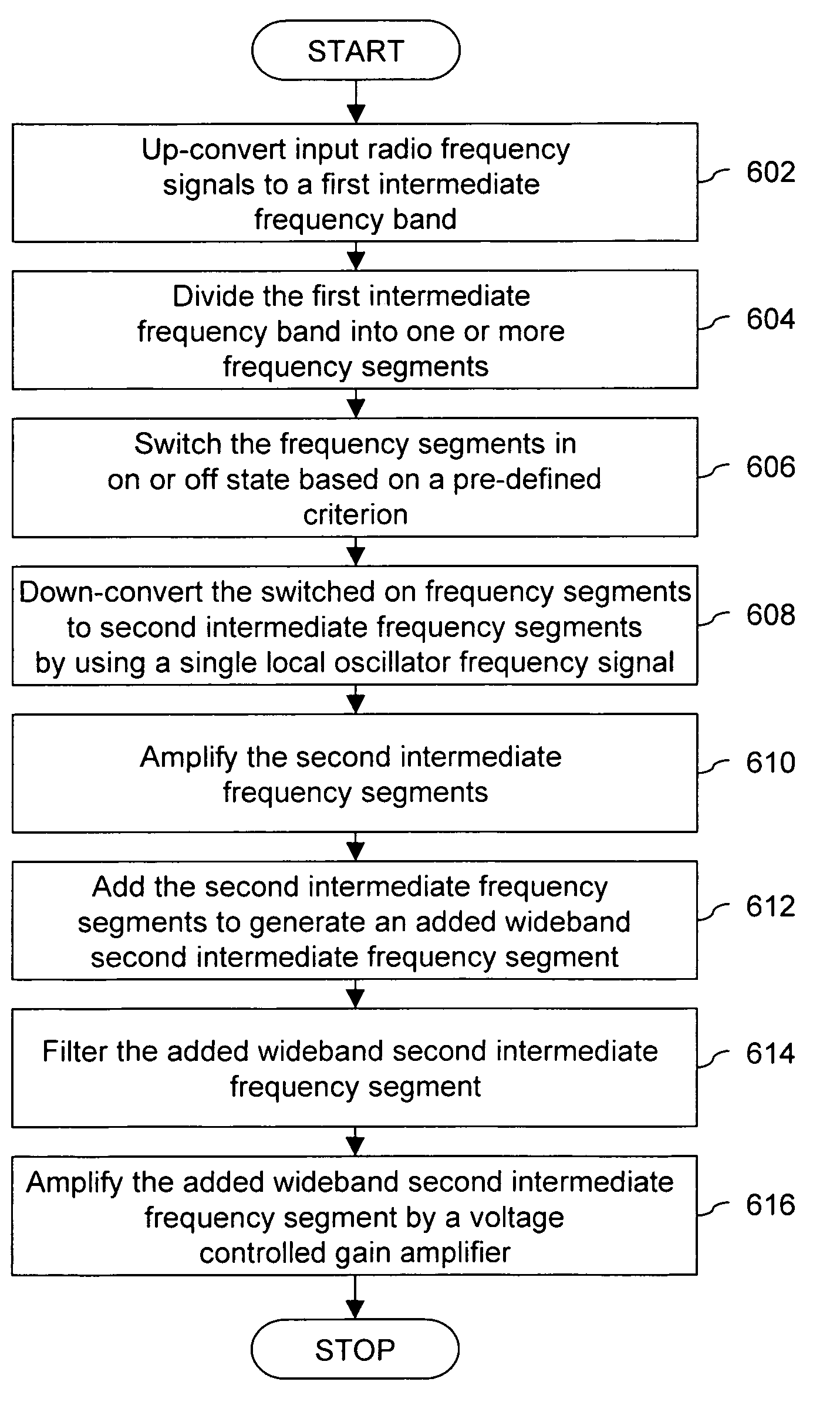
[0022]Various embodiments of the invention provide a system and method for frequency conversion in a frequency-conversion receiver. The frequency-conversion receiver receives input RF signals carrying multiple channels. The frequency-conversion receiver allows processing of multiple channels by converting the input RF signals to an IF band. The IF band is then processed and further down-converted, filtered and amplified, according to the required channels for the desired final output IF signals.

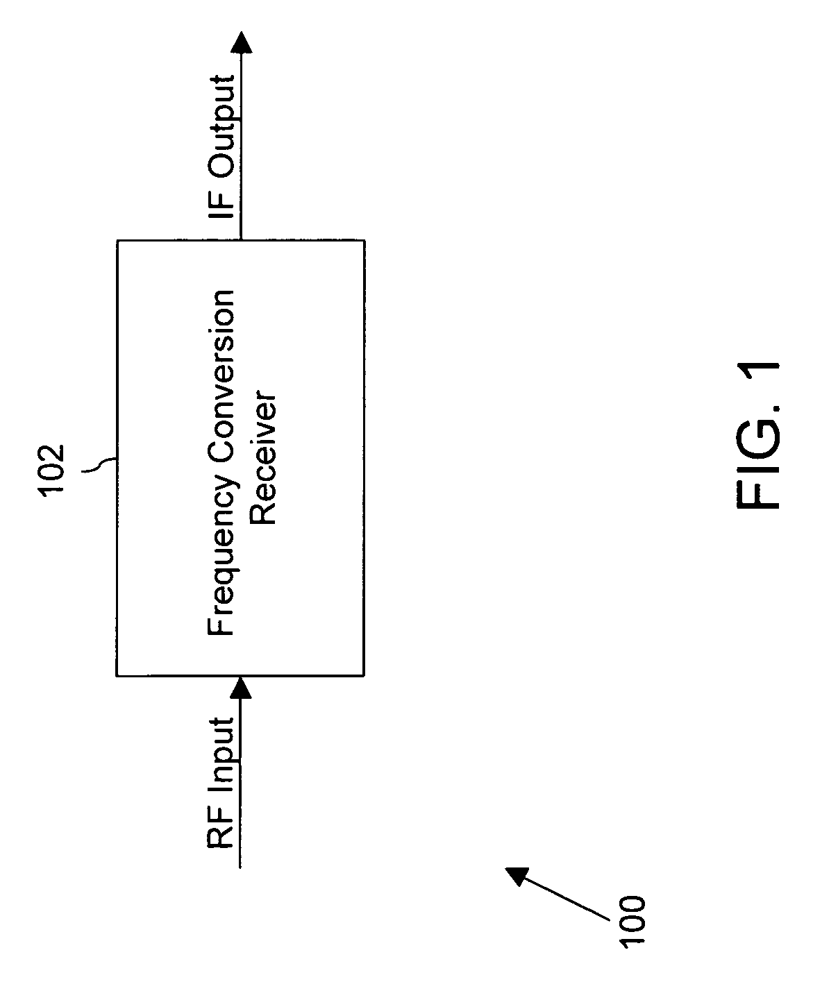
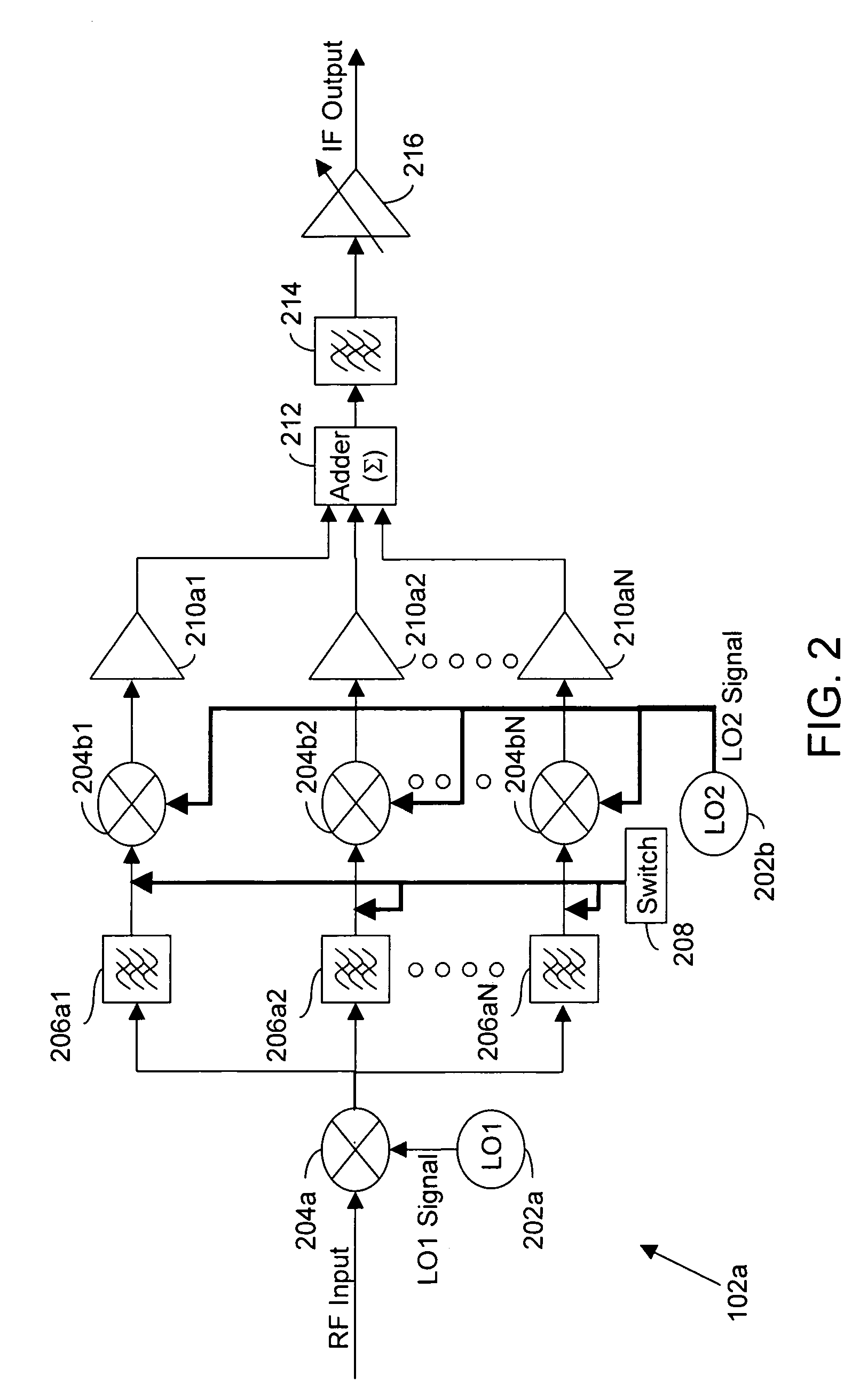
[0023]FIG. 1 is a block diagram of an environment 100 in which various embodiments of the invention may be practiced. Environment 100 includes a frequency-conversion receiver 102. Frequency-conversion receiver 102 converts the input RF signals to desired output IF signals. Frequency-conversion receiver 102 performs frequency multiplexing to provide frequency signals carrying multiple channels. The desired output IF signals are further provided to a demodulator. The demodulator, for example, a...


PUM


Abstract

A system and method for frequency conversion in a frequency-conversion receiver is disclosed. The frequency-conversion receiver receives input RF signals carrying multiple channels. The frequency-conversion receiver converts the input RF signals to a wide IF band. The IF band is further processed by dividing the IF band into one or more frequency segments or by selecting a wideband frequency segment from the IF band. The wideband frequency segment or the one or more frequency segments are further down-converted, filtered and amplified to provide desired output IF signals, based on the number of channels required in the output IF signals.

Description

BACKGROUND OF THE INVENTION[0001]The present invention generally relates to the field of frequency-conversion receivers. More specifically, it relates to a system and method for frequency multiplexing in frequency-conversion receivers.[0002]Frequency-conversion receivers are used in various electronic devices, such as televisions (TV), radios for transmission and reception of RF signals at particular frequencies. A frequency-conversion receiver receives transmitted signals for example, a band of radio frequency (RF) signals carrying multiple channels and converts the RF signals to signals of a different frequency. The frequency-conversion receiver processes these transmitted signals to provide the desired output signals to the demodulator. The demodulator demodulates the desired output signals to extract information. Examples of frequency-conversion receivers include a heterodyne receiver, a super heterodyne receiver, a double-conversion receiver, and the like.[0003]The frequency-co...

Claims


Application Information

Patent Timeline
Patent Type & Authority Patents(United States)
IPC IPC(8): H04N5/46
CPCH04B1/28
Inventor VYSYARAJU, RAJAHCANELO, JULIOARMOUR, CHARLESBAYRUNS, JOHNLEBLEBICIOGLU, HAKAN
Owner SKYWORKS SOLUTIONS INC
Why Eureka
Try Eureka