Atmospheric infrasonic sensing from an aircraft

a technology of infrasonic sensing and airframe, which is applied in the direction of optical prospecting, clear air turbulence detection/forecasting, instruments, etc., can solve the problem that the noise at scales larger than the aperture of the sensor cannot be mitigated with a single sensor, the spatial averaging of pneumatic transmission lines becomes ineffective beyond certain wind speeds, and the inability to observe and locate better, so as to achieve the effect of superior signal-to-noi ratio ratio ratio ratio ratio ratio ratio ratio ratio ratio ratio ratio ratio ratio ratio ratio ratio ratio ratio ratio ratio ratio ratio ratio ratio ratio ratio ratio ratio ratio ratio ratio ratio ratio ratio ratio ratio ratio ratio ratio ratio ratio ratio ratio ratio ratio ratio ratio ratio

Active Publication Date: 2020-03-03
THE UNITED STATES OF AMERICA AS REPRESENTED BY THE SECRETARY OF THE NAVY
View PDF51 Cites 11 Cited by
  • Summary
  • Abstract
  • Description
  • Claims
  • Application Information

AI Technical Summary

Benefits of technology

[0028]The present invention's infrasonic technology features, inter alia, implementation of fiber optic sensing so as to create an aircraft infrasonic sensor. Taking advantage of the large size of a typical commercial aircraft, exemplary inventive practice strategically places at least one fiber optic sensor sufficiently long to average out “background noise” while uncoupling seismic infrasound from the sensory readings. A superior signal-to-noise ratio is generated, all while on a moving platform. Advantageously, inventive placement of one or more infrasonic sensors on an aircraft provides the ability to better observe and locate the source of infrasound generating phenomenon, especially in cases of severe weather. To the inventor's knowledge, no acoustic measurement of infrasound has previously been made possible from an aircraft in motion.

Problems solved by technology

The primary drawback of Bedard's sensor is that it is stationary and on the earth's surface.
Another drawback of Bedard's sensor is that the pneumatic transmission line spatial averaging becomes ineffective beyond certain wind speeds.
However, a drawback of the sensor of Shams and Zuckerwar is that it has a small spatial aperture; therefore, incoherent noise at scales larger than the sensor's aperture cannot be mitigated with a single sensor.

Method used


Image

  • Atmospheric infrasonic sensing from an aircraft
  • Atmospheric infrasonic sensing from an aircraft
  • Atmospheric infrasonic sensing from an aircraft

Examples


Embodiment Construction

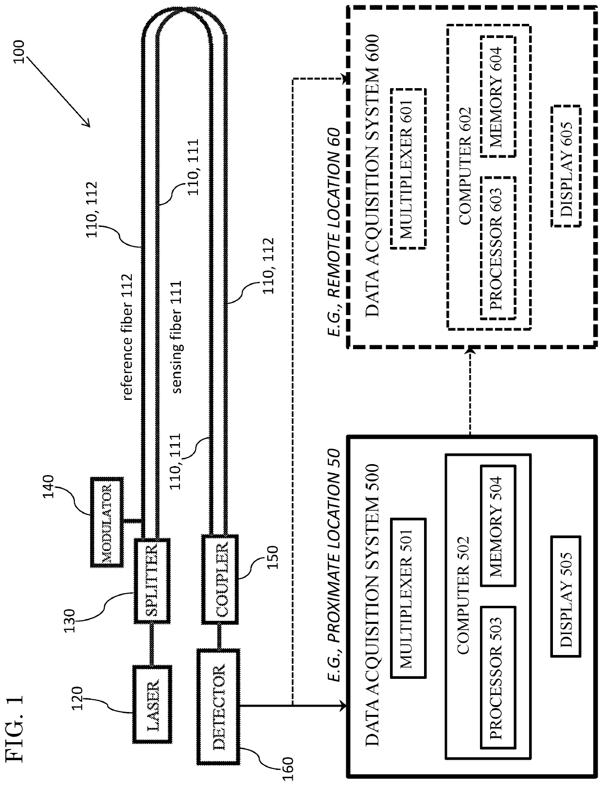
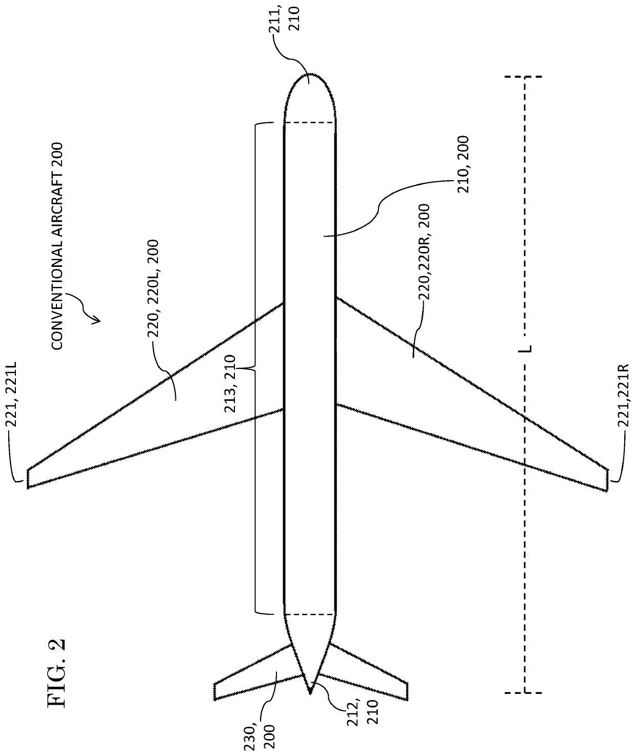
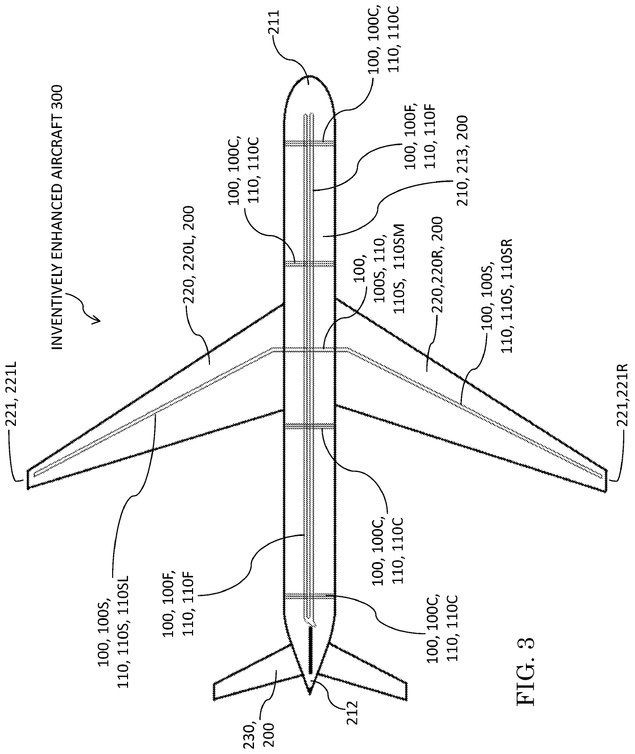
[0045]With reference to FIG. 1, a main objective of exemplary practice of the present invention is to measure low frequency acoustic energy at altitude in the atmosphere. Exemplary inventive practice features, inter alia, effectuation of such infrasonic measurements through association of interferometric optical fibers with one or more aircraft such as, for example, commercial aircraft 200 shown in FIG. 2. Exemplary embodiments of the present invention implement one or more interferometric infrasound sensors such as interferometric infrasound sensor 100 shown in FIG. 1. According to exemplary inventive practice, multiple infrasound sensors 100 situated on an aircraft 200 provide a means for determining amplitude and direction of incident acoustic energy.

[0046]The embodiment shown in FIG. 1 of an inventive interferometric fiber-optic sensing device 100 includes an optical fiber pair 110, a laser 120, a splitter 130, a modulator 140, a coupler 150, and a photodetector 160. The pair 11...


PUM


Abstract

Exemplary practice of the present invention provides an air vehicle and at least one interferometric double-path fiber optic sensor connected with the air vehicle. Each fiber optic sensor includes a pair of optical fibers, viz., an optical sensing fiber and an optical reference fiber, in a parallel and propinquus relationship. The paired optical fibers of each fiber optic sensor are attached to the air vehicle either (i) circumferentially around the fuselage or (ii) lengthwise along the fuselage or (iii) span-wise along the wings and across the fuselage, and are configured whereby the sensing fiber is exposed to the atmosphere and the reference fiber is not. Each fiber optic sensor senses atmospheric infrasound but does not sense atmospheric wind noise, which is negated by incoherency associated with design lengthiness of the optical fiber pair. Noise and strain due to temperature, vibration, and propulsion are neutralized via interferometric common mode rejection.

Description

STATEMENT OF GOVERNMENT INTEREST[0001]The invention described herein may be manufactured and used by or for the Government of the United States of America for governmental purposes without payment of any royalties thereon or therefor.CROSS-REFERENCE TO RELATED APPLICATIONS[0002]This United States patent application is related to U.S. patent application Ser. No. 15 / 669,050, filing date 4 Aug. 2017, hereby incorporated herein by reference, entitled “Atmospheric Infrasonic Sensing from an Array of Aircraft,” inventor Alexey Titovich, now U.S. Pat. No. 10,365,089 B1, issue date 30 Jul. 2019.BACKGROUND OF THE INVENTION[0003]“Infrasound” is conventionally regarded as sound at frequencies less than 20 Hz. Airborne infrasound is thus defined by pressure waves at frequencies below 20 Hz. The human ear cannot hear infrasound, but at higher amplitudes it can be felt by the body. These waves propagate with little attenuation over long distances, carrying information about the state of the atmos...

Claims


Application Information

Patent Timeline
Patent Type & Authority Patents(United States)
IPC IPC(8): G01C21/20G01W1/10G08G5/00G05D1/10G01W1/00G05D1/00H04L29/08
CPCG05D1/0005G01C21/20G01W1/10G05D1/101H04L67/025G08G5/0091H04L67/10G01W2001/003G01V7/00G01V8/02G01W1/08H04L67/12
Inventor TITOVICH, ALEXEY
Owner THE UNITED STATES OF AMERICA AS REPRESENTED BY THE SECRETARY OF THE NAVY
Why Eureka
Try Eureka