

Photosensor and focus detecting device
a technology of focus detection and photosensor, which is applied in the field of photosensors, can solve the problems of not describing the arrangement of photoreceptors for a plurality, and achieve the effects of reducing control circuits, reducing power consumption, and reducing the chip area of photosensors
- Summary
- Abstract
- Description
- Claims
- Application Information
AI Technical Summary
Benefits of technology
Problems solved by technology
Method used
Image


Examples
first exemplary embodiment
[0032]A first exemplary embodiment of the present invention will be described below.
[0033]FIG. 1 is a schematic view showing a configuration of an image pickup system according to the first exemplary embodiment. Referring to FIG. 1, the image pickup system includes an image pickup apparatus 100. The image pickup apparatus 100 includes the following components 101 to 116. That is, the image pickup apparatus 100 includes an erect-image optical system 101 that forms a finder optical system, an eyepiece 102, and a finder screen 103. A mirror 104 deflects a part of an imaging light beam toward the finder optical system 101. A mirror 105 deflects the imaging light beam passing through the mirror 104 toward a focus detecting device that will be described below. An image pickup element 106 controls an image pickup operation of the image pickup apparatus 100. A shutter 107 shields the image pickup element 106 from light. A built-in flash 108 is stored in the image pickup apparatus 100.
[0034]...
second exemplary embodiment
[0132]A second exemplary embodiment of the present invention will be described below. Descriptions of the same components as those in the first exemplary embodiment are omitted.
[0133]FIG. 12 shows an example configuration of a sensor 1090 provided in a focus detecting device 109 according to the second exemplary embodiment.
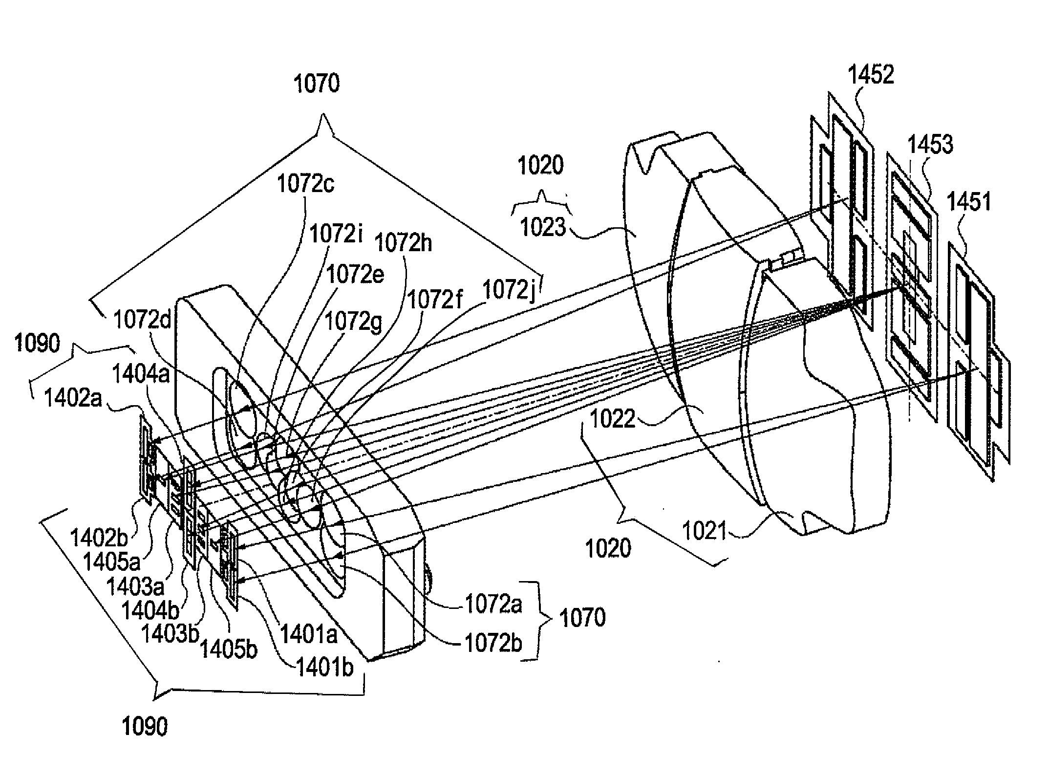
[0134]FIG. 13 shows the relationship among a predetermined image plane of an image pickup apparatus, an image-reforming lens 1070, the sensor 1090, and images formed by the image-reforming lens 10170 on the sensor 1090.
[0135]An imaging relationship of the focus detecting device 109 will be described below with reference to FIGS. 6, 12, and 13.
[0136]In FIG. 13, line sensors 1201a to 1212a and 1201b to 1212b, environment-detecting photoreceptors 1301a to 1304a and 1301b to 1304b, and projection images 1401a to 1404a and 1401b to 1404b formed by image-reforming lens elements 1072a to 1072h are the same as those shown in FIG. 5. Therefore, descriptions thereof are omi...
third exemplary embodiment
[0155]A third exemplary embodiment of the present invention will be described below. Descriptions of the same components as those in the first exemplary embodiment are omitted.
[0156]FIG. 15 shows a configuration of a sensor 1090 provided in a focus detecting device 109 according to the third exemplary embodiment.
[0157]FIG. 16 shows a configuration of an image-reforming lens 1070 provided in the focus detecting device 109.
[0158]FIGS. 17 and 18 show the relationship among a predetermined image plane of an image pickup apparatus according to this embodiment, the image-reforming lens 1070, the sensor 1090, and images formed on the sensor 1090 by the image-reforming lens 1070.
[0159]An imaging relationship of the focus detecting device 109 will be described below with reference to FIGS. 15, 16, 17, and 18.
[0160]FIGS. 17 and 18 schematically show a field mask 1450 disposed near a predetermined image plane of the image pickup apparatus, the image-reforming lens 1070, a sensor chip 1091 prov...
PUM
 Abstract
Description
Claims
Application Information