Electric Ballast and a Lighting System

a technology of electric ballast and lighting system, which is applied in the direction of point-like light source, transportation and packaging, lighting and heating apparatus, etc., can solve the problems of high temperature of heat generating parts (high temperature parts) of ballast, the possibility of wrong operation remains, and the lamp can be noisy further reduced

Inactive Publication Date: 2008-05-29
MATSUSHITA ELECTRIC WORKS LTD
View PDF10 Cites 9 Cited by
  • Summary
  • Abstract
  • Description
  • Claims
  • Application Information

AI Technical Summary

Benefits of technology

[0012]In an enhanced embodiment, the electric ballast further comprises a filter which is located between the power converter and the igniter and has two series capacitors connected in p

Problems solved by technology

Because there is a possibility that noise generated from a discharge lamp caused by polarity inversing of a lamp current enters each portion of a ballast through the wires to cause wrong operation of devices.
However, if the ballast housing does not have a shield function, said possibili

Method used


Image

  • Electric Ballast and a Lighting System
  • Electric Ballast and a Lighting System
  • Electric Ballast and a Lighting System

Examples


Embodiment Construction

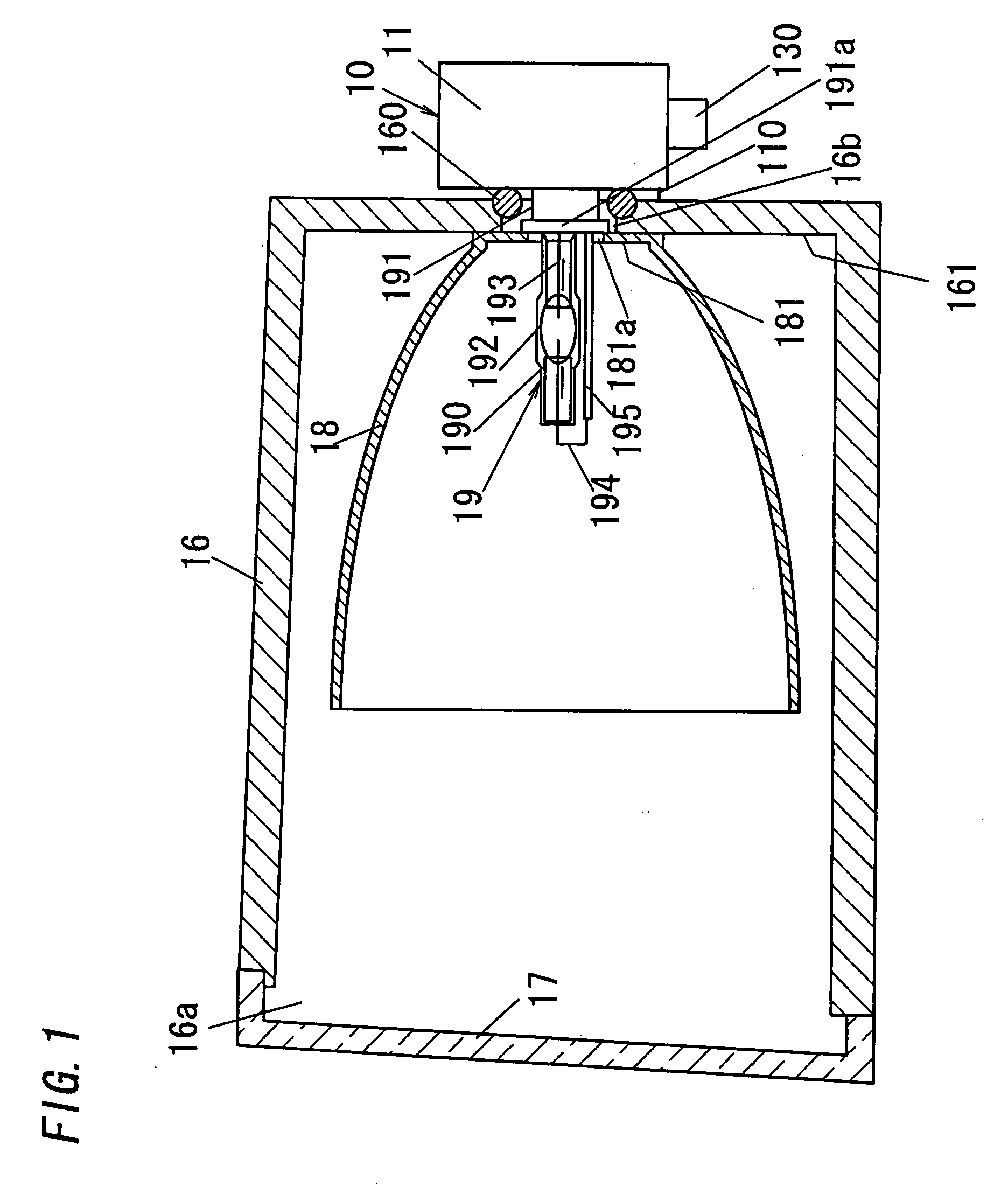
[0031]FIG. 1 shows a lighting system in accordance with a first embodiment of the present invention. The lighting system of FIG. 1 is a vehicle lighting system such as headlights, fog lights or the like, and is, for example, a fog light in the first embodiment. This system is formed of a lamp housing 16, a front lens 17, a reflector 18, a discharge lamp 19 and an electric ballast 10.

[0032]The lamp housing 16 is, for example, a case in which the reflector 18 and the discharge lamp 19 are put, and has a front opening 16a and a rear opening 16b. The opening 16b is formed at the bottom 161 of the housing 16. The housing 16 is formed of conductive materials such as, for example, metal or the like. In case of fog lights, the lamp housing is usually connected with flame ground. The housing 16 is also connected with flame ground.

[0033]The front lens 17 is formed of materials for translucency to close the front opening 16a. The lens 17 is fixed on the edge of the front opening 16a with, for ...


PUM


Abstract

An electric ballast attached to the outside of a lighting system. The system comprises a lamp housing with front and rear openings, a front lens closing the front opening, a discharge lamp put in the housing, and a reflector that reflects light of the lamp toward the lens. The ballast comprises: a ballast housing which closes the rear opening and is connected with frame ground via at least one of the lamp housing and the reflector; a lamp socket and an igniter, put in the front of the ballast housing; and a power converter put in the ballast housing. The output of the converter is connected with the socket, which directly connects with the lamp, and the igniter is connected between them. Heat generating parts of the converter are put in the rear of the ballast housing, and the rear functions as a radiator.

Description

TECHNICAL FIELD[0001]The invention relates to lighting systems such as, for example, headlights, fog lights or the like, and in particular, to an electric ballast for the system.BACKGROUND ART[0002]A prior art device described in Japanese Patent Application Publication No. 2001-338506 includes an electric ballast for a vehicle lighting system that comprises a lamp housing with front and rear openings, a front lens closing the front opening, a discharge lamp put in the housing, and a reflector put in the housing to reflect light of the lamp toward the lens. The ballast is formed of a ballast housing closing said rear opening, and an inverter and an igniter which are put in the ballast housing. The ballast is also electrically connected with the lamp via a wire harness (wires and connectors) and a lamp socket.[0003]Another prior art device described in Japanese Patent Application Publication No. 2002-367414 includes an electric ballast for a vehicle lighting system that comprises a la...

Claims


Application Information

Patent Timeline
IPC IPC(8): F21V29/00F21Y101/00
CPCF21S48/1109F21V29/004F21S48/328F21S48/1186F21V29/503F21S41/172F21S41/192F21S45/48F21S45/50F21V23/026
Inventor HAMADA, HIDEKIKIDO, SHOJIRO
Owner MATSUSHITA ELECTRIC WORKS LTD
Why Eureka
Try Eureka