Fiber and nanofiber spinning apparatus

a technology which is applied in the field of fiber and nanofiber spinning apparatus, can solve the problems of limited control over these expensive dies, inability to melt other polymers such as acrylics, and limited options in the fiber spinning area, so as to achieve low cost, versatile and cost-effective spinning methods

a technology which is applied in the field of fiber and nanofiber spinning apparatus, can solve the problems of limited control over these expensive dies, inability to melt other polymers such as acrylics, and limited options in the fiber spinning area, so as to achieve low cost, versatile and cost-effective spinning methods

US20080136054A1Active Publication Date: 2008-06-12MEMPRO LTD

Image

  • Fiber and nanofiber spinning apparatus
  • Fiber and nanofiber spinning apparatus
  • Fiber and nanofiber spinning apparatus

Examples


Embodiment Construction

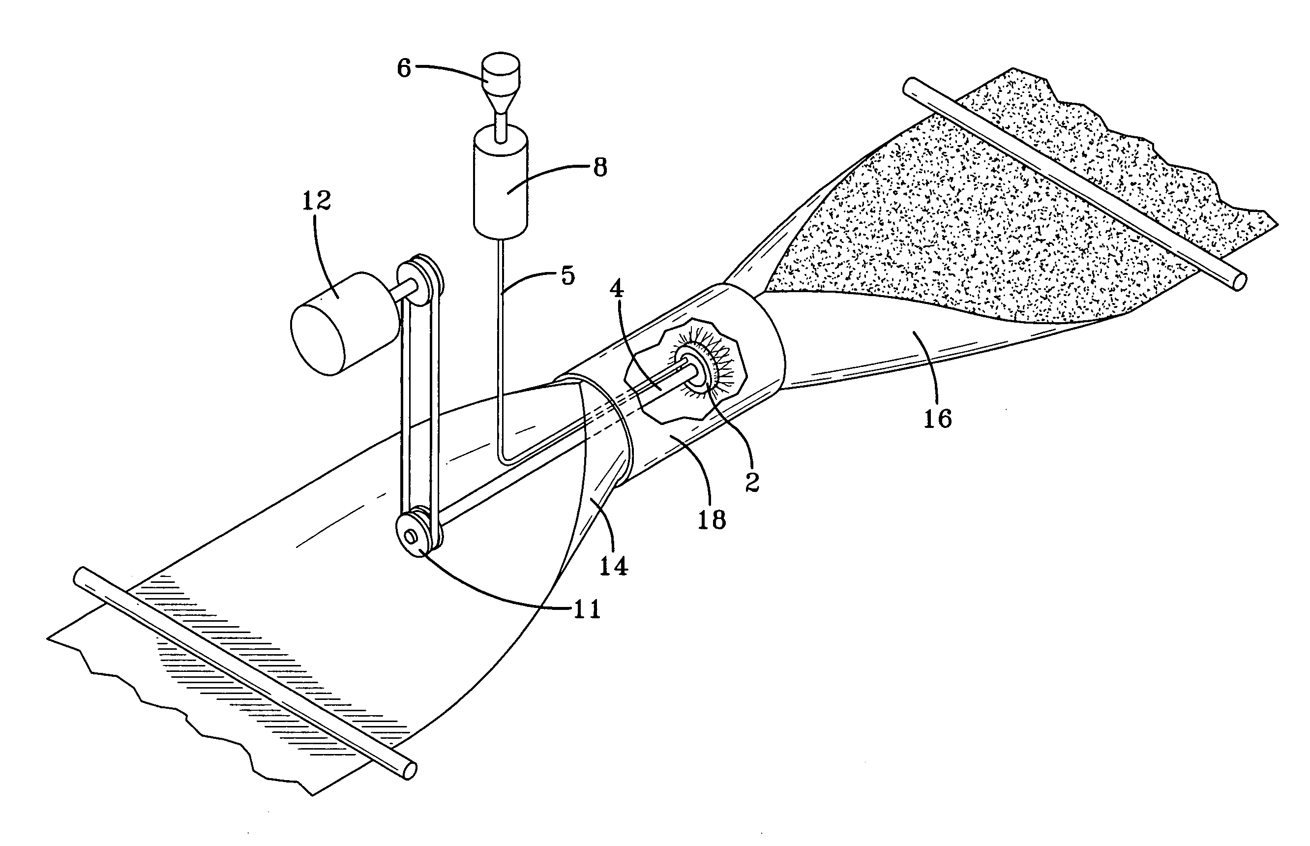
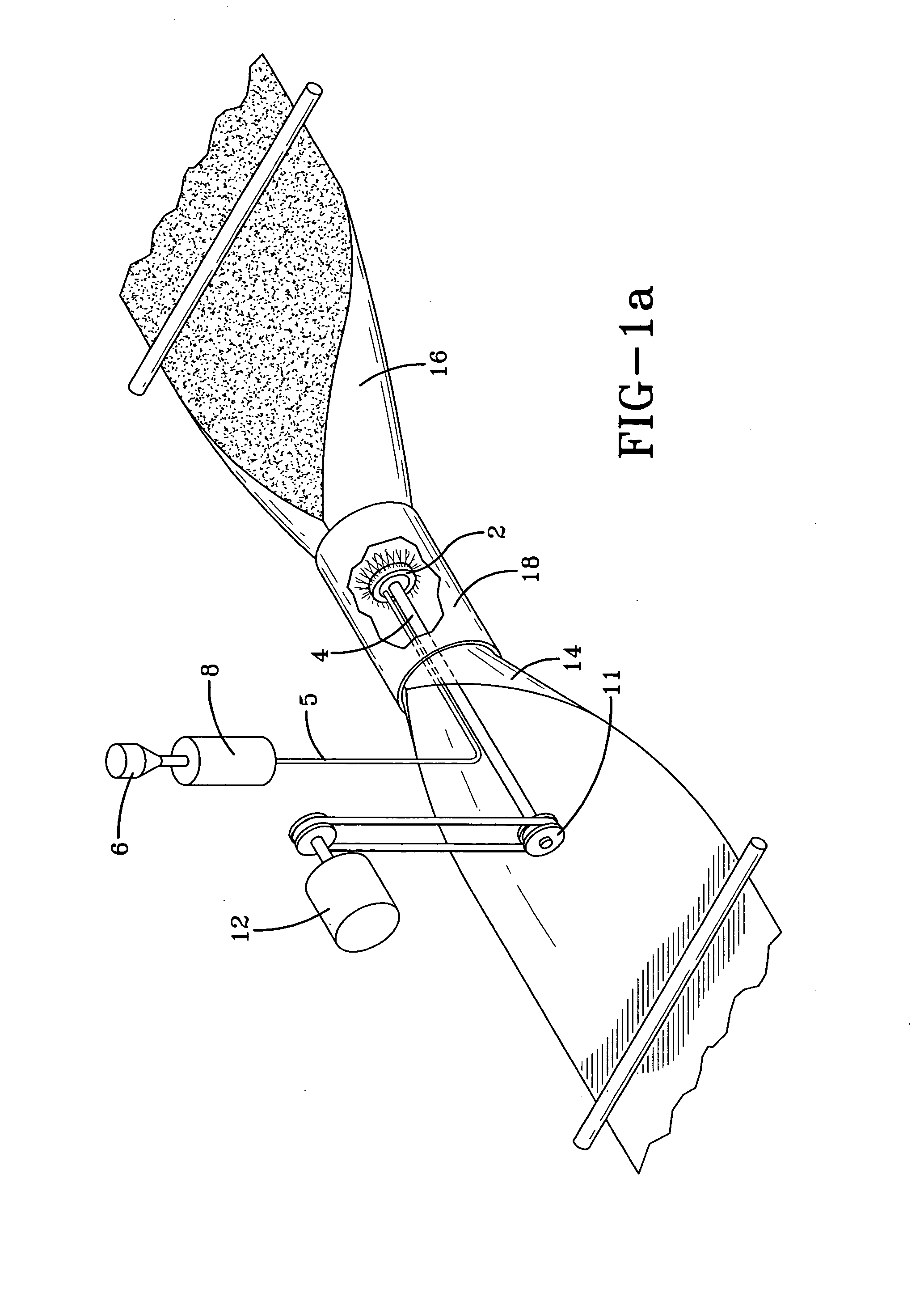
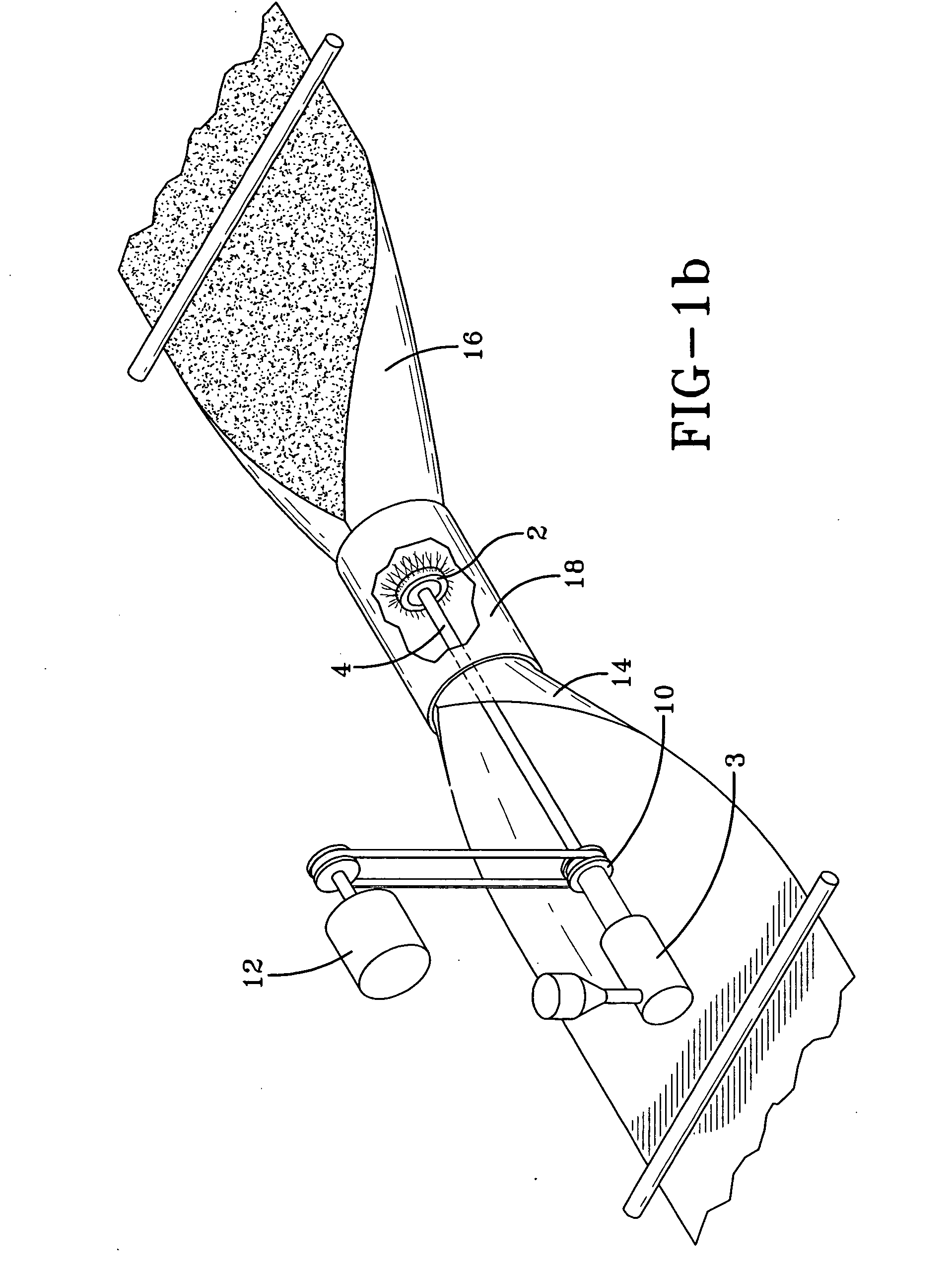
[0031]The present invention generally relates to an apparatus for extruding and spinning fibers and relates more particularly to the production of a homogeneous web of fibers. The plate configuration on the apparatus is of particular importance, as it allows production of nanofibers and other larger fibers by centrifugal force. The stacked, thin plates and the interchangeability of these plates, along with the variations of slots, holes or grooves for extrusion of fluid materials is novel to the art of spinning fibers. The device operates by stacking the plates and allowing a serpentine flow for an even, uniform pressure balance and improved fluid distribution. Stacked, “bridged” plates with small serpentine flow throughways can also be strategically constructed as built-in filters to material passing through the plates. The interchangeability aspects of the plates allows for a variety of configurations to be employed. These variations include, but are not limited to, changing the s...


PUM

PropertyMeasurementUnit
pressureaaaaaaaaaa
angleaaaaaaaaaa
diameteraaaaaaaaaa

Abstract

The present invention relates to a method and an apparatus for spinning fibers, or fiberizers, using a rotary fiber-making die system made up of thin plates, embodied by a housing fixture, configured and stacked to define slots, channels and / or grooves through which the material used to make the fibers will flow. The die system allows for the production of different size and types of fibers, including nanofibers having a diameter of less than 1 micron, and facilitates a variety of cost effective methods for extrusion. The use of plates means the dies can be manufactured cost effectively, with easier clean-outs, replacements and / or variations.

Description

BACKGROUND OF THE INVENTION[0001]This invention relates to a method and an apparatus for spinning fibers, or fiberizers, using a rotary fiber-making die system made up of thin plates, embodied by a housing fixture, configured and stacked to define slots, channels and / or grooves through which the material used to make the fibers will flow. The die system allows for the production of different size and types of fibers, including nanofibers having a diameter of less than 1 micron, and facilitates a variety of cost effective methods for extrusion. The use of plates means the dies can be manufactured cost effectively, with easier clean-outs, replacements and / or variations.[0002]Thermoplastic resins and glass have been extruded to form fibers and webs for many years. The nonwoven webs produced are commercially useful for many applications including diapers, feminine hygiene products, medical and protective garments, filters, geotextiles, insulation, ceiling tiles, battery separator media ...

Claims


Application Information

Patent Timeline
12 Jun 2008
Publication
US20080136054A1
IPC
D01D5/08; D01D5/18; B29C48/05; B29C48/12
CPC
C03B37/045; D01D4/06; D01D5/18; B29C47/0014; B29C47/30; B29C47/0064; B29C47/026; B29C47/065
Inventors
FABBRICANTE, ANTHONY; FABBRICANTE, JACK S.