Power control system and method

a power control system and power technology, applied in the field of system and a power control method, can solve the problems of transformer overheating, continuous consumption of power, transformer overheating, etc., and achieve the effect of avoiding overheating of power adapters and reducing power consumption

Active Publication Date: 2008-06-19
COMPAL ELECTRONICS INC
View PDF4 Cites 23 Cited by
  • Summary
  • Abstract
  • Description
  • Claims
  • Application Information

AI Technical Summary

Benefits of technology

[0010]Accordingly, the present invention is directed to a power control system, applicable for controlling the turn-on / off of the power entering a power adapter according to power on / off status of the system and the status of the battery, so as to reduce the power consumption or avoid overheating of the power adapter.
[0011]The present invention is further directed to a power control method, applicable for controlling the turn-on / off of the power entering the power adapter according to the battery saturation status, so as to avoid the service life of the battery from being shortened because of continuing receiving power.
[0017]As the present invention adopts a power control system and method for controlling the power on / off of the power adapter by means of detecting the power on / off signal by a controller or according to the connection status and the electric quantity of the battery, the power consumption can be effectively reduced, and the overheating situation of the power adapter that may shorten the service life because of continuing receiving power can be avoided.

Problems solved by technology

When the power of the lithium battery is not sufficient, it only needs to connect the electronic product to a transformer, which can charge the lithium battery.
However, the current transformers available on the market do not have the functions of automatically controlling the power on / off of the power thereof.
Even when the electronic product is powered off, the transformer still continuously runs, and thus the power is continuously consumed.
As a result, the power is continuously consumed and the energy is wasted by the transformer, and thus leading to the overheating of the transformer and shortened service life of the transformer.
However, the above method can only tackle the problem on the surface, not at the root.
Each time when powering off the transformer, the user must manually turn off the switch of the transformer personally, which is not only considerably inconvenient for the user, but the situations that the user forgets to turn off the switch of the transformer also occurs, and thus, the switch disposed for the transformer are almost non-existed.

Method used


Image

  • Power control system and method
  • Power control system and method
  • Power control system and method

Examples


Embodiment Construction

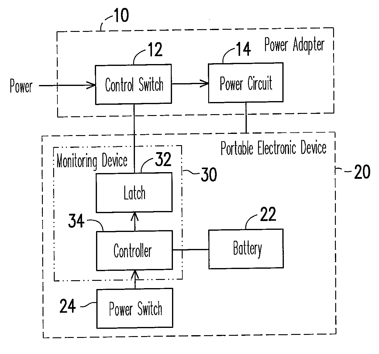
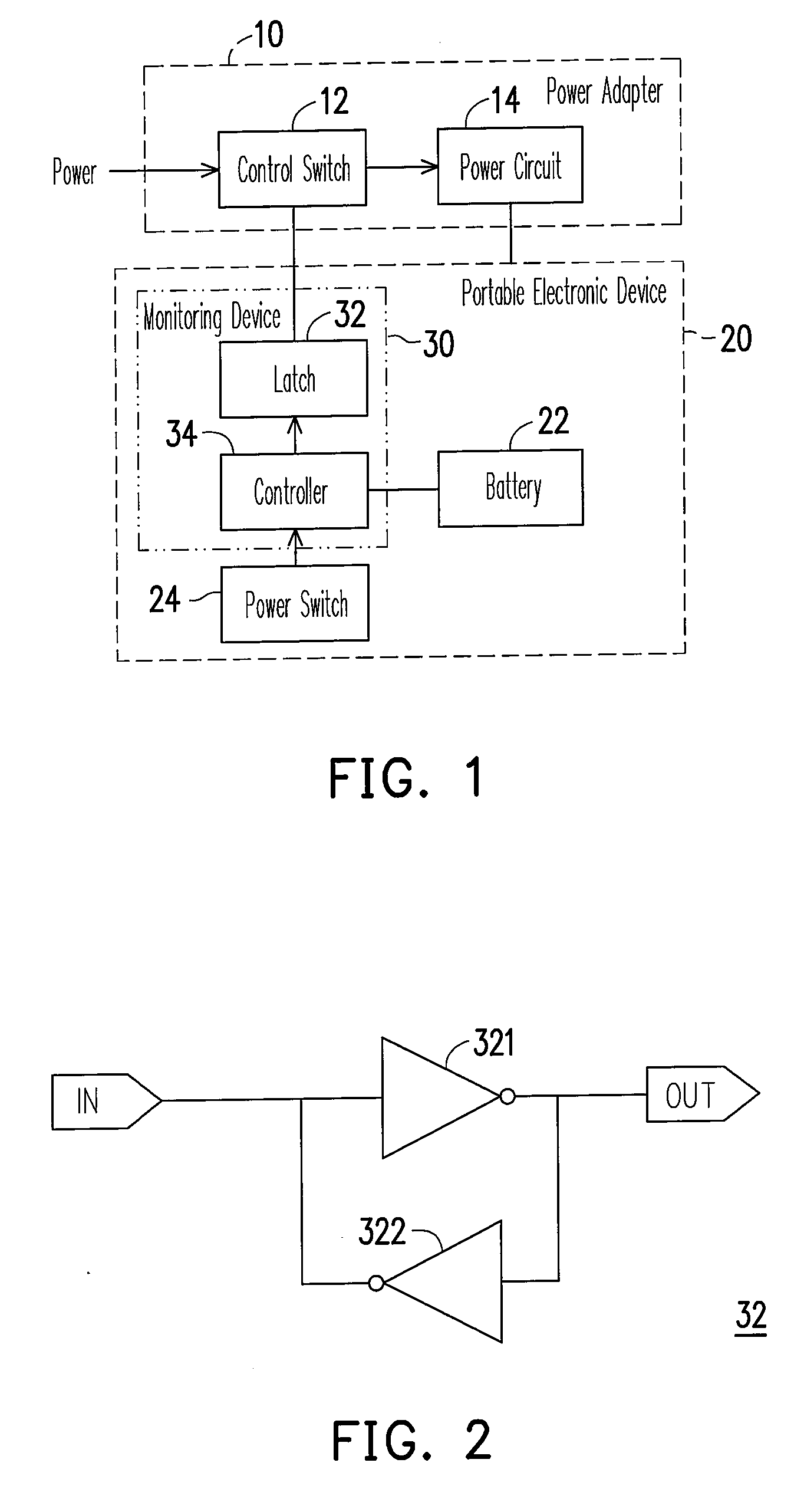
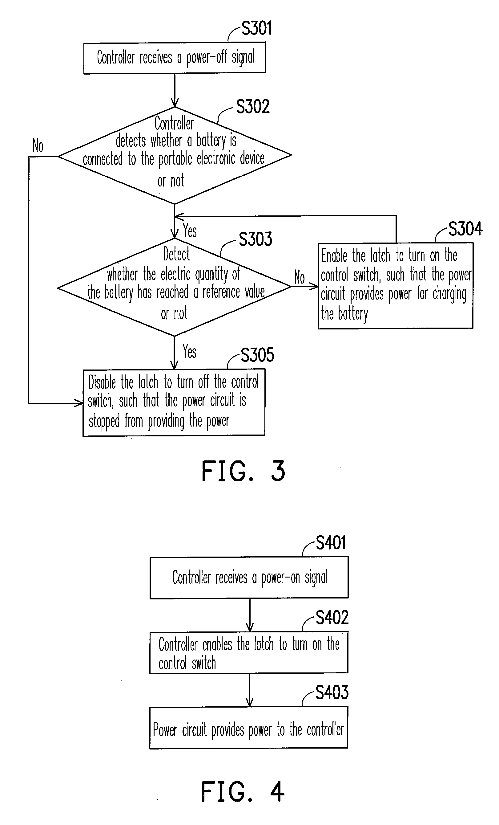
[0025]FIG. 1 is a block diagram of a power control system according to an embodiment of the present invention. Referring to FIG. 1, the structure of the system in the present embodiment can be divided into two parts, wherein one part is a power adapter 10, and the other part is a portable electronic device 20. The power adapter 10 generally refers to a power adapter having the functions of stepping up and stepping down the voltage, converting between alternating current (AC) and direct current (DC), and frequency converting, for example, (but not limited to) a transformer, a frequency converter, and an AC / DC converter. The power adapter 10 includes a control switch 12 and a power circuit 14. The control switch 12 is coupled to a power, which is used to control the ON / OFF state of the power according to an external instruction, so as to determine whether to provide an AC for the power circuit 14 to convert into a voltage required by the portable electronic device 20. For example, whe...


PUM


Abstract

A system and a method for power control are provided. In the present invention, a control switch is disposed in a power adapter, which is turned on / off by a monitoring device disposed in a portable electronic device. As a result, the power inputted into the power adapter can be controlled, and thus the power consumption during the portable electronic being shut down is reduced. In addition, the present invention controls the power providing for a battery according to a detected power on / off signal and the electric quantity of the battery. The control switch is turned off to stop the power adapter from providing power when the electric quantity of the battery reaches a reference value. Therefore, the overheating situation of the portable electronic device or the battery that may shorten their service life because of continuing receiving power can be avoided.

Description

CROSS-REFERENCE TO RELATED APPLICATION[0001]This application claims the priority benefit of Taiwan application serial no. 95146579, filed on Dec. 13, 2006. All disclosure of the Taiwan application is incorporated herein by reference.BACKGROUND OF THE INVENTION[0002]1. Field of the Invention[0003]The present invention relates to a system and a method for power control. More particularly, the present invention relates to a system and a method for power control by controlling a power to be switched on or off.[0004]2. Description of Related Art[0005]As the rapid development of science and technology, electronics have been increasingly prevailing. Portable electronics, such as notebook computers, personal digital assistants (PDAs) are the most favorite ones among the users, due to the features of being light, thin, short, and small and having multiple functions.[0006]As for the portable electronic products, the power supply is an important part. In order to provide the portable electroni...

Claims


Application Information

Patent Timeline
Patent Type & Authority Applications(United States)
IPC IPC(8): G06F1/32
CPCG06F1/32
Inventor SHEN, YI-HUNGCHANG, TSANG-MING
Owner COMPAL ELECTRONICS INC
Why Eureka
Try Eureka