Method and apparatus for controlling the cut register of a web-fed rotary press

a technology of rotary presses and cutting registers, which is applied in the direction of web handling, transportation and packaging, printing, etc., can solve the problems of relatively high mechanical and electrical complexity of apparatuses of this typ

Active Publication Date: 2008-06-26
MANROLAND WEB SYST
View PDF12 Cites 11 Cited by
  • Summary
  • Abstract
  • Description
  • Claims
  • Application Information

AI Technical Summary

Benefits of technology

[0006]It is an object of the invention to provide a simple method of controlling the cutting register error in a web-fed rotary press.
[0013]It is significant that, when the limits of a control variable, e.g., the control variable ω3w, are exceeded, the control of the part register error Y*13 is transferred from the controller of the clamping point 3 to a controller 1.1 of the clamping point 1, that is to say the angle of the clamping point 1 is tracked and the excessively small or excessively large value of ω3w is moved back into the permissible range. The tracking of the angle of the clamping point 1 is carried out for all operating states in which ω3w lies within the limits by an adaptation element 1.2, a set point for the readjustment of the angle α1w being calculated with the aid of a mathematical model, as a result of which a sufficient reserve of the manipulated variable, e.g., the control variable ω3w or lead of the clamping point 3, is always ensured. In the mathematical model, the relationship between the lead change needed for the correction of the part register error Y*13 and the resultant correction value α1w is calculated. The tracking of the angle of the clamping point 1 is advantageously carried out slowly as compared with the control of Y*13, as a result of which ghosting arising from excessively fast position changes of the printing units (clamping point 1) is avoided and decoupling of the control loops is achieved.
[0017]Because of the special characteristics of the control system, the cutting register control with the aid of the lead of a clamping point is dynamically faster than in the case of the conventional solution by a register roll, since a change in the lead at the relevant clamping point replaces a path change. A significant advantage of this register control with the aid of the lead of a clamping point is that barely any wear of the mechanical transmission elements occurs, as would be the case in dynamically fast control with the aid of changing the path of an actuating roll. A further advantage is that the control engineering expenditure in the case of this cutting register error control with the aid of the lead of a clamping point is lower than in the case of a dynamically fast control with the aid of the path change of an actuating roll.
[0018]The parameters that enter into the cutting register error control system are largely independent of the properties of the rotary press. Furthermore, the cutting register accuracy can be increased substantially by the new method.
[0019]The tracking of the web tension may also be achieved with the aid of the dancer roll force, this being determined from the pressure of an associated pneumatic cylinder, the force being measured, supplied to a web tension controller and compared with the force set point, the output variable from the controller either being directly the manipulated variable for the pneumatic cylinder or the set point F01w, if there is a subordinate control loop for the input web tension F01. A web tension control loop for the web tension F01 can also replace the dancer roll. This force adaptation always ensures that the force change which occurs quickly because of a disturbance being controlled out is dissipated relatively slowly as compared with this control.

Problems solved by technology

Apparatuses of this type are afflicted with a relatively high mechanical and electrical complexity.

Method used


Image

  • Method and apparatus for controlling the cut register of a web-fed rotary press
  • Method and apparatus for controlling the cut register of a web-fed rotary press
  • Method and apparatus for controlling the cut register of a web-fed rotary press

Examples


Embodiment Construction

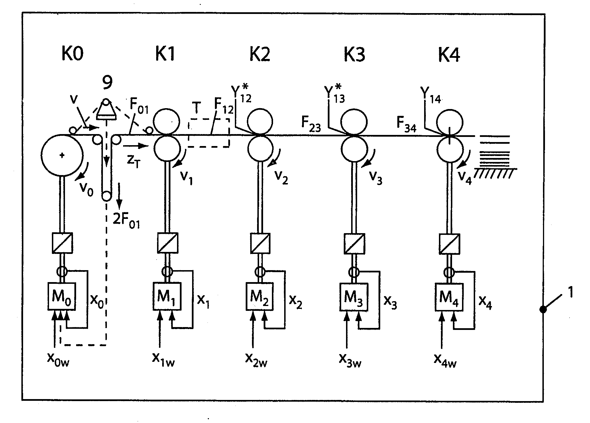
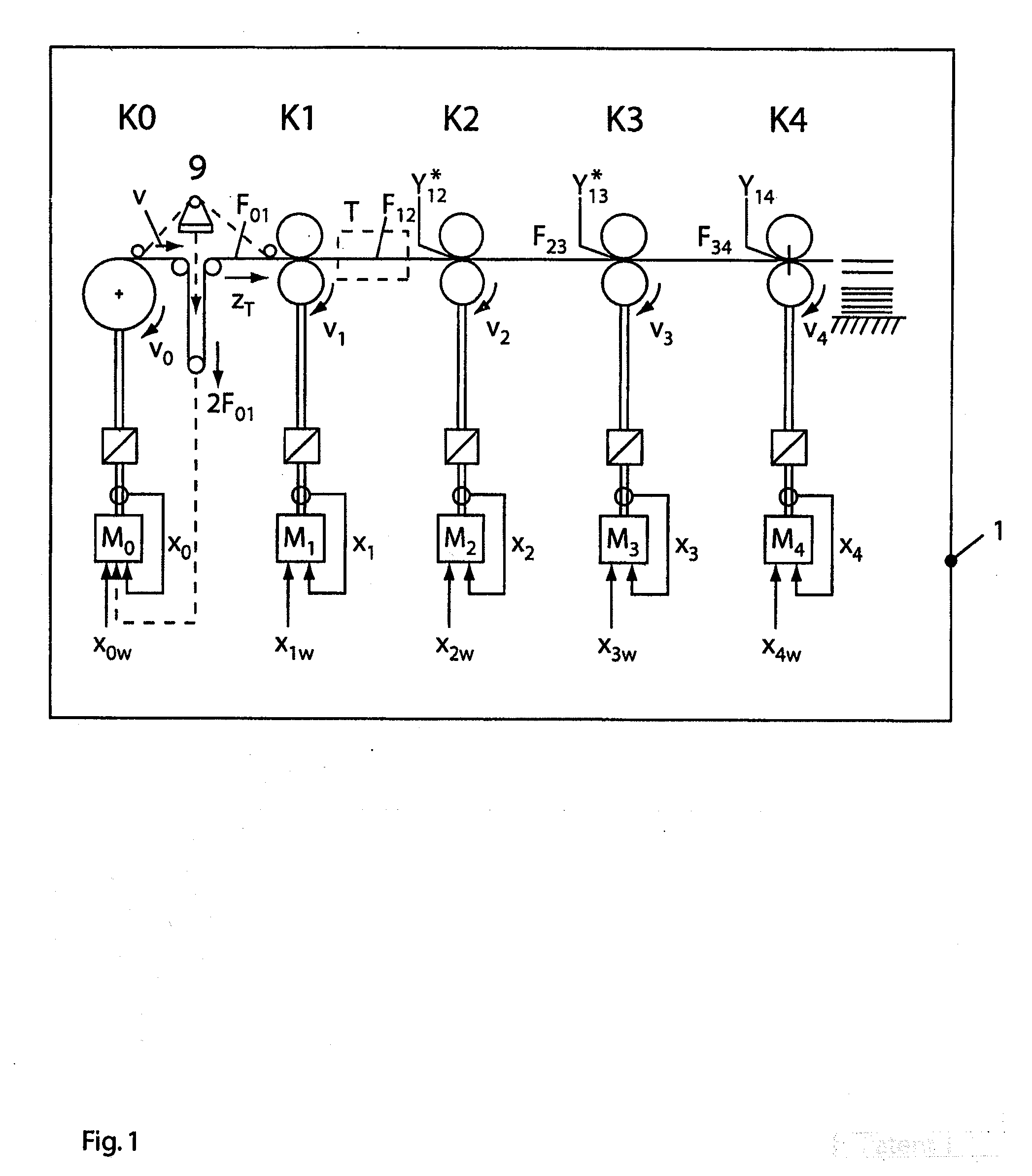
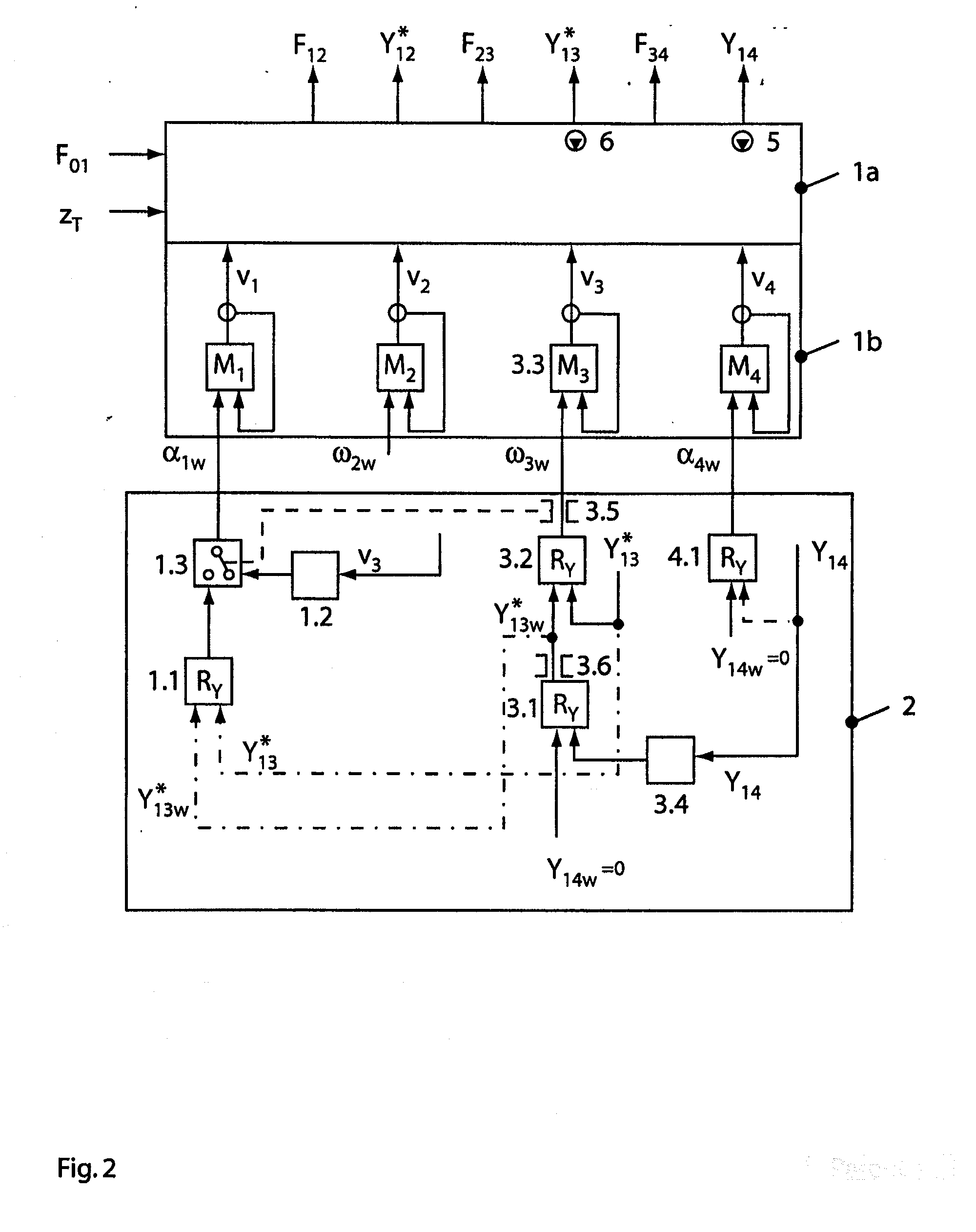
[0027]The function of the present invention will be explained using the exemplary embodiments on a four-roll system. It is pointed out that, in a real press, as many printing units as desired, that is to say, for example, four printing units, of a web-fed offset illustration press or newspaper press or another type of rotary press may replace a clamping point 1 of the illustrated four-roll system. The principle of register correction described in the following text by two control loops superimposed on each other, one being given as actual value the register error measured immediately before the knife cylinder, the other the error from a clamping point located further in front, can be transferred with the same effect to all rotary presses.

Functional Explanation of the Four-Roll System

[0028]The four-roll system of FIG. 1 is a simplified form of a rotary press, in particular a web-fed offset press. In FIG. 1, clamping point 1 (K1) may, for example, represent all the printing units foll...


PUM

PropertyMeasurementUnit
angular velocityaaaaaaaaaa
tension forceaaaaaaaaaa
rotational speedaaaaaaaaaa

Abstract

To control the cutting register of a web in a web-fed rotary press with little expenditure, a specific item of image information or a measuring mark of a printed web is registered by at least one sensor. The sensor generates a registration signal which is supplied to a control device. The registration of the image information or measuring marks is carried out immediately before or on a knife cylinder. A cutting register error is determined from the registration information and the position of the knife cylinder is influenced to correct the determined cutting register error.

Description

CROSS REFERENCE TO RELATED APPLICATION[0001]This application is a continuation of U.S. patent application Ser. No. 10 / 913,247 which was filed with the U.S. Patent and Trademark Office on Aug. 6, 2004. Priority is claim on patent application No. 103 35 888.9 filed in Germany on Aug. 6, 2003.BACKGROUND OF THE INVENTION[0002]1. Field of the Invention[0003]The invention relates to a method and apparatus for controlling the cutting register on a web running through a web-fed rotary press.[0004]2. Description of the Related Art[0005]In web-fed rotary presses, it is known to use an actuating roll which can be moved in linear guides as an actuating element for correcting errors in the position of the cutting register on a web. In this case, the actuating roll changes the paper path length between two draw units to correct the cutting register error. Register rolls of this type are shown, for example, in DE 85 01 065 U1. The adjustment is generally carried out by an electric stepping motor. ...

Claims


Application Information

Patent Timeline
Patent Type & Authority Applications(United States)
IPC IPC(8): B41F1/34B41F13/24B65H23/188
CPCB41F13/025B65H23/1882B65H2511/112B65H2515/31B65H2801/21B65H2220/02B65H2220/01B65H2220/03Y10T83/04Y10T83/041Y10T83/159
Inventor BRANDENBURG, GUNTHERGEISSENBERGER, STEFANKLEMM, ANDREAS
Owner MANROLAND WEB SYST
Why Eureka
Try Eureka