Eureka AIR delivers breakthrough ideas for toughest innovation challenges, trusted by R&D personnel around the world.

Multi-Function Portable Gas Stove

Inactive Publication Date: 2008-08-07
SU ALBERT
View PDF4 Cites 6 Cited by
  • Summary
  • Abstract
  • Description
  • Claims
  • Application Information

AI Technical Summary

Benefits of technology

[0013]Thereby, in the present invention, the multi-stage folding support units pivotally connected to the burner, when folded and laid aside the burner, help to fix a gas bottle on the burner so that a user can conveniently carry or store the gas stove and the gas bottle. On the other hand, the support units also serve to support cookers with different sizes by providing an adjustable supporting area defined by the folded or stretched support units. Also, the support units serve to upright or slant the burner so that the disclosed gas stove is adaptive to a relatively high cooker or heating a food from a side thereof so as to prevent oil or juice generated by the heated food from dropping on the burner directly and thereby maintain the burner in cleanness and burner ports in an unobstructed state, resulting in an extended use life of the burner.
[0014]Furthermore, the heat sinks equipped on each said first folding arm of the present invention as motioned above enable thermal conduction when laying aside the burner so as to rapidly guide out and distribute excessive heat on the burner, thereby preventing the exterior of the burner from being excessively hot and in turn ensuring safe use.
[0015]Moreover, the elastic element of the present invention helps to draw each said support unit to perform various folding positions easily and helps to fix the folded support units in position.
[0016]Additionally, the reflective tray provided around the burner of the present invention serves to prevent heat radiation of the stove fire from dissipation and further reflect the heat radiation to the cooker to enhance the heating efficiency of the stove fire.
[0017]Besides, the extending claw mounted on the third joint of the first folding arm of the support unit in the present invention can freely rotate over the burner to function as a support for cookers with different sizes.

Problems solved by technology

Besides, those conventional portable gas stoves are somewhat of bulkiness and thus inconvenient for storage while the spare gas bottles taken out along with the portable gas stoves cause extra trouble for carrying and storing the same.
In addition, since pan supports of the conventional portable stove directly settled on the reservoir thereof for supporting cookers, when stretched, usually provide a limited supporting area, the pan supports are handicapped in supporting a relatively large cooker.
In a case where a relatively large cooker is put thereon and filled with foods, the cooker will easily capsize due to the narrow supporting area.
Though some of the mentioned gas stoves have detachable pan supports, such design provides no help in carrying or storing the gas stoves.
Meantime, since supporting areas defined by the pan supports are limited; these gas stoves are also unsuitable for large cookers.
That is to say, when these gas stoves are used with a relatively large cooker or a cooker filled with foods, the cooker is subject to overturn because of its unbalanced placement.
Also, as the gas reservoir and the portable gas stove are independent components but not formed as an integral, they have to be carried separately and this is inconvenient to users.
Additionally, when any one of the aforementioned conventional portable gas stoves is used to cook, foods to be cooked have to be place right on the stove fire for acquiring sufficient heat, yet however, oil or sauce released by the heated foods may directly drop on the burner to stain or clog the burner and undesirably snuff out the stove fire or cause the burner become difficult to be cleaned.

Method used


Image

  • Multi-Function Portable Gas Stove
  • Multi-Function Portable Gas Stove
  • Multi-Function Portable Gas Stove

Examples


Embodiment Construction

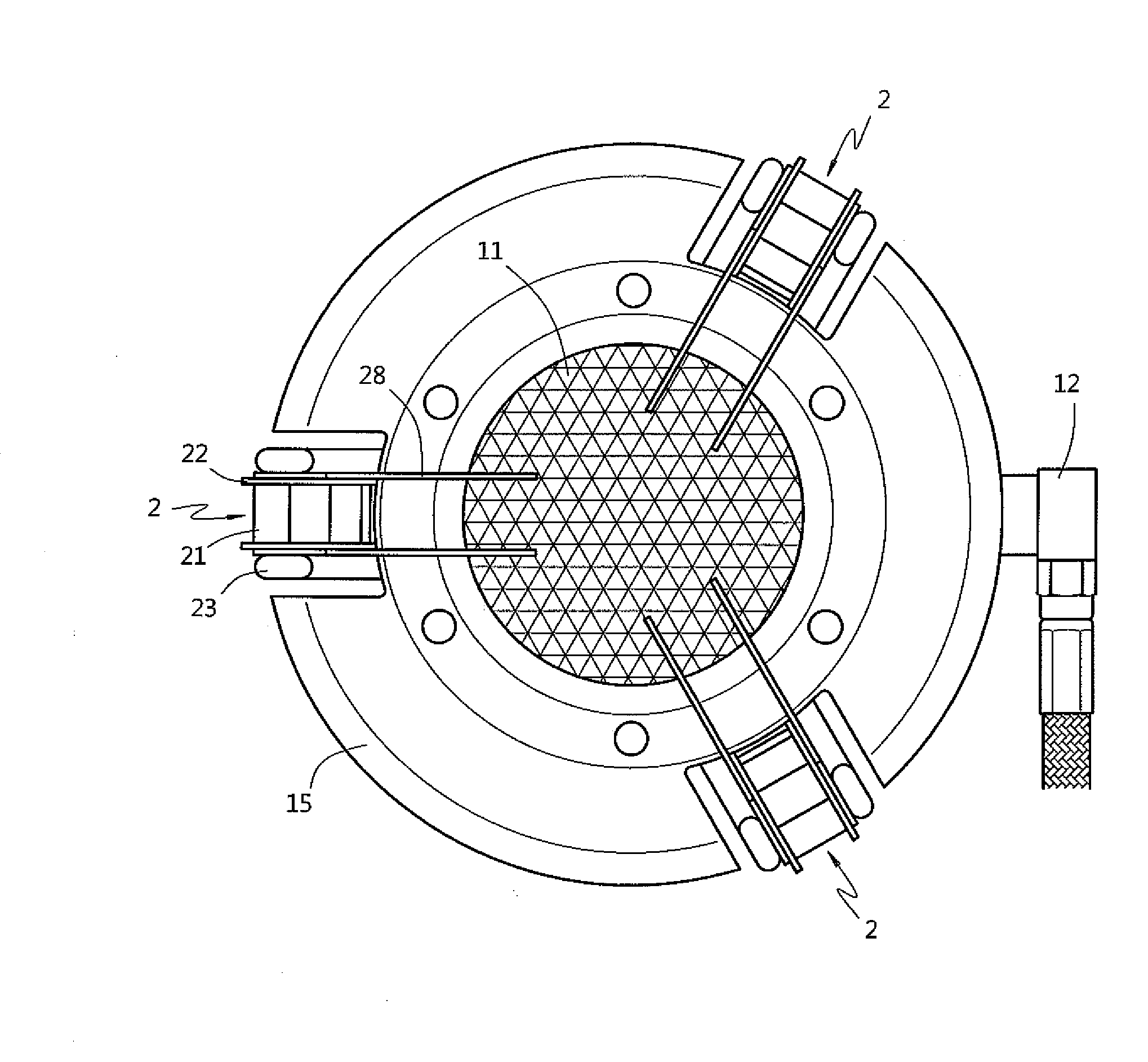
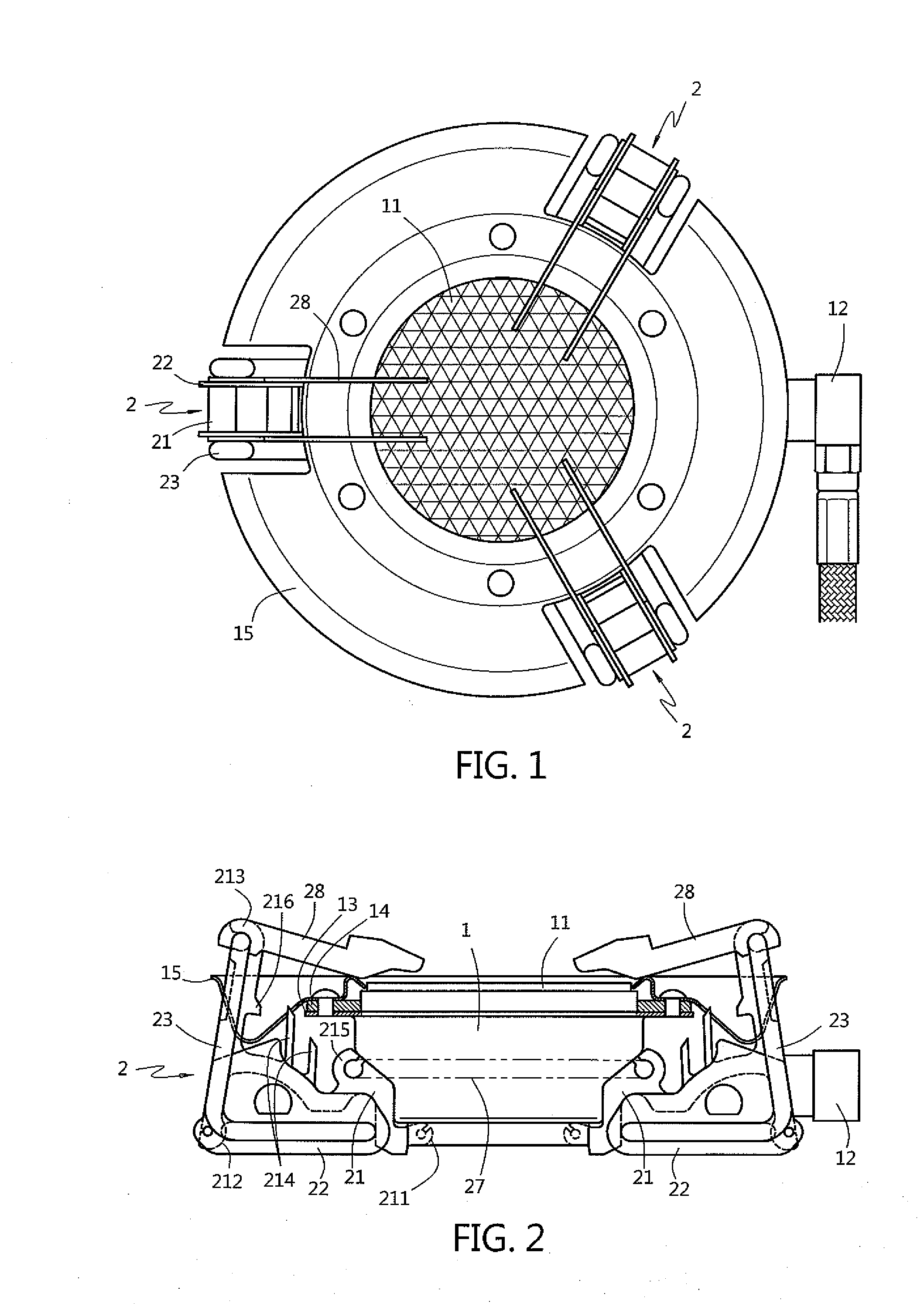
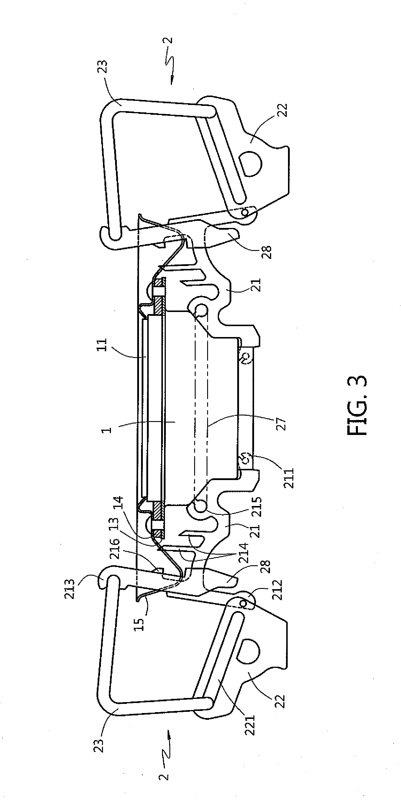
[0030]Please refer to FIGS. 1, 2 and 3. Therein, plural sets of support units 2 are radially provided around a bottom of a burner 1. The burner 1 is equipped with a core 11 made of far infrared ceramics and a nozzle 12 positioned at one side thereof for introducing gas. A flange 13 is formed at an upper periphery of the burner 1 and is covered by a heat-insulating element 14 and a reflective tray 15 that has gaps for allowing the support units 2 to pass therethrough. The heat-insulating element 14 and the reflective tray 15 are fixedly connected to the flange 13 while an inner edge of the reflective tray 15 abuts against and thereby position the core 11.

[0031]Besides, each of the support units 2 primarily comprises a first folding arm 21, a second folding arm 22 and a third arm 23 which are pivotally connected mutually. Therein, the first folding arm 21 has three joints 211, 212, 213 and a plurality of heat sinks 214. The first joint 211 of the first folding arm 21 is such connected...


PUM


Abstract

A multi-function portable gas stove with folding pan supports comprises a burner that is surrounded by a reflective tray for reflecting a heat radiation of a stove fire of the portable gas stove on a cooker, and plural sets of support units pivotally connected to the burner. Each of the support units comprises a first folding arm that has three joints and heat sinks while drawn by an elastic element. The first joint of the first folding arm is pivotally connected to the burner, and the second joint is pivotally connected by one end of a second folding arm. A third folding arm is pivotally connected between the third joint of the first folding arm and a sliding groove formed on the second folding arm. Furthermore, a rotatable claw is pivotally mounted on the third joint of each of the first folding arm. Thereby, the portable gas stove is adaptable to cookers of different sizes by variably folding the support units and the burner can be uprighted to a higher altitude or slanted so as to allow a user to cook in different ways. When the support units are folded and retracted, a gas bottle can be fixed on the burner for convenient carrying and storing.

Description

BACKGROUND OF THE INVENTION[0001]1. Technical Field[0002]The present invention relaters to a portable gas stove having a burner attached by multi-stage folding support units for supporting cookers with various sizes and uprighting or slanting the burner so as to allow a user to cook or burn foods in different ways.[0003]2. Description of Related Art[0004]A conventional portable gas stove typically has a refillable gas reservoir and a burner directly mounted on the reservoir, such as that disclosed in Taiwan Patent Publications M279821, 241884, 117001, 36695 or 34546. Though those conventional portable gas stoves are advantageous by being gas-refillable, a gas bottle is nevertheless indispensable for resupplying gas in an extended use case. Besides, those conventional portable gas stoves are somewhat of bulkiness and thus inconvenient for storage while the spare gas bottles taken out along with the portable gas stoves cause extra trouble for carrying and storing the same. In addition...

Claims


Application Information

Patent Timeline
IPC IPC(8): F24C3/08
CPCF24C3/14Y02B40/166F24C15/08Y02B40/00F24C3/04
Inventor SU, ALBERT
Owner SU ALBERT
Why Eureka
Eureka Blog
Learn More