System for Damping Thermo-Acoustic Instability in a Combustor Device for a Gas Turbine

a technology of thermo-acoustic instability and combustor device, which is applied in the direction of machines/engines, mechanical equipment, light and heating equipment, etc., can solve the problems of thermo-acoustic instability, undesirable vibration in the turbine, damage to the components of the turbine, etc., and achieve the effect of proven effectiveness

Inactive Publication Date: 2008-09-11
ANSALDO ENERGIA SPA
View PDF8 Cites 45 Cited by
  • Summary
  • Abstract
  • Description
  • Claims
  • Application Information

AI Technical Summary

Benefits of technology

[0013]A purpose of the present invention is to provide a system for damping thermo-acoustic instability in a combustor device for a gas turbine which will be free from the drawbacks described and will be of proven effectiveness.
[0014]Another purpose of the invention is to provide a system for damping thermo-acoustic instability in a combustor device for a gas turbine that will be of contained overall dimensions and, in general, such as to enable application thereof to any annular combustion chamber of a known type, that will enable ease of installation and maintenance, contained costs, high reliability and a structure such as to enable a simple and fast regulation of the volume of the resonator or resonators.
[0020]In this way, the invention surprisingly achieves the purposes outlined above. In fact, the geometry described maximizes the range of frequencies which can be dampened, rendering unnecessary the adoption of any “active” feedback control system, which could reduce the reliability of the system. Furthermore, said range of frequencies that can be dampened can be easily regulated as a function of the fuel used and other operating parameters which can vary case by case, in the step of starting of the gas turbine, simply by varying just once the pre-set volume defined internally by each resonator casing.
[0021]The system according to the invention hence presents the following advantages:

Problems solved by technology

However, on the basis of the results of some verifications, it may be stated that the annular geometry associated to high densities of thermal yield can favour onset of phenomena of thermo-acoustic instability.
Said oscillations can bring about undesirable vibrations in the turbine and damage its components.
However, these methods, which are prevalently of an active type, have moving members and / or need to undergo operations of control and adjustment during the operating cycle of the gas turbine.
The mechanism for regulating the volume of the resonator proves moreover very delicate.
However, the position in which the resonators should be mounted on the combustion chamber to be effective is not clarified.
Furthermore, the volume of the resonator is not adjustable, so that the operating frequency is fixed.
In theory, the system is flexible, but at the expense of complications in terms of plant design and instrumentation, which limits the reliability thereof in an environment that is particularly critical, as regards temperature and pressure, as is that of a gas turbine.
Consequently, if the range of frequencies in which the resonator is effective is very restricted, as proves likely from the drawings (a range which, however, in this document is not defined, even indirectly), the damping could be insufficient in various operating conditions.
Furthermore, the position of installation chosen for the resonator, as has been experimentally found by the technicians of the present applicant, is not the optimal position for its operation.
In addition, for reasons of encumbrance, application of the resonator in the way indicated in EP 0597138A1 is not possible on combustion chambers different from the one hypothesized: for example, in the case of the majority of known turbines it would be necessary to redesign the air chamber and the combustion chamber.
Finally, it is to be highlighted that all the known solutions described above do not define the range of frequencies in which the resonator is effective, nor the effectiveness of damping of the pressure waves.
Consequently, the state of the art that illustrates the application of passive resonators / dampers to combustion chambers of gas turbines in practice merely provides nothing but speculations as regards the possible effectiveness of the solutions proposed, without in effect providing to the person skilled in the branch any indication supported by experimental findings.

Method used


Image

  • System for Damping Thermo-Acoustic Instability in a Combustor Device for a Gas Turbine
  • System for Damping Thermo-Acoustic Instability in a Combustor Device for a Gas Turbine
  • System for Damping Thermo-Acoustic Instability in a Combustor Device for a Gas Turbine

Examples


example of application

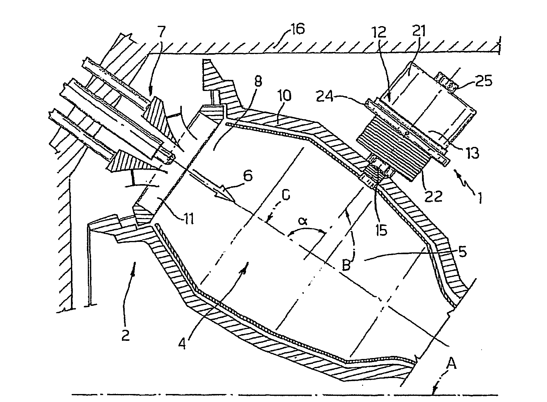
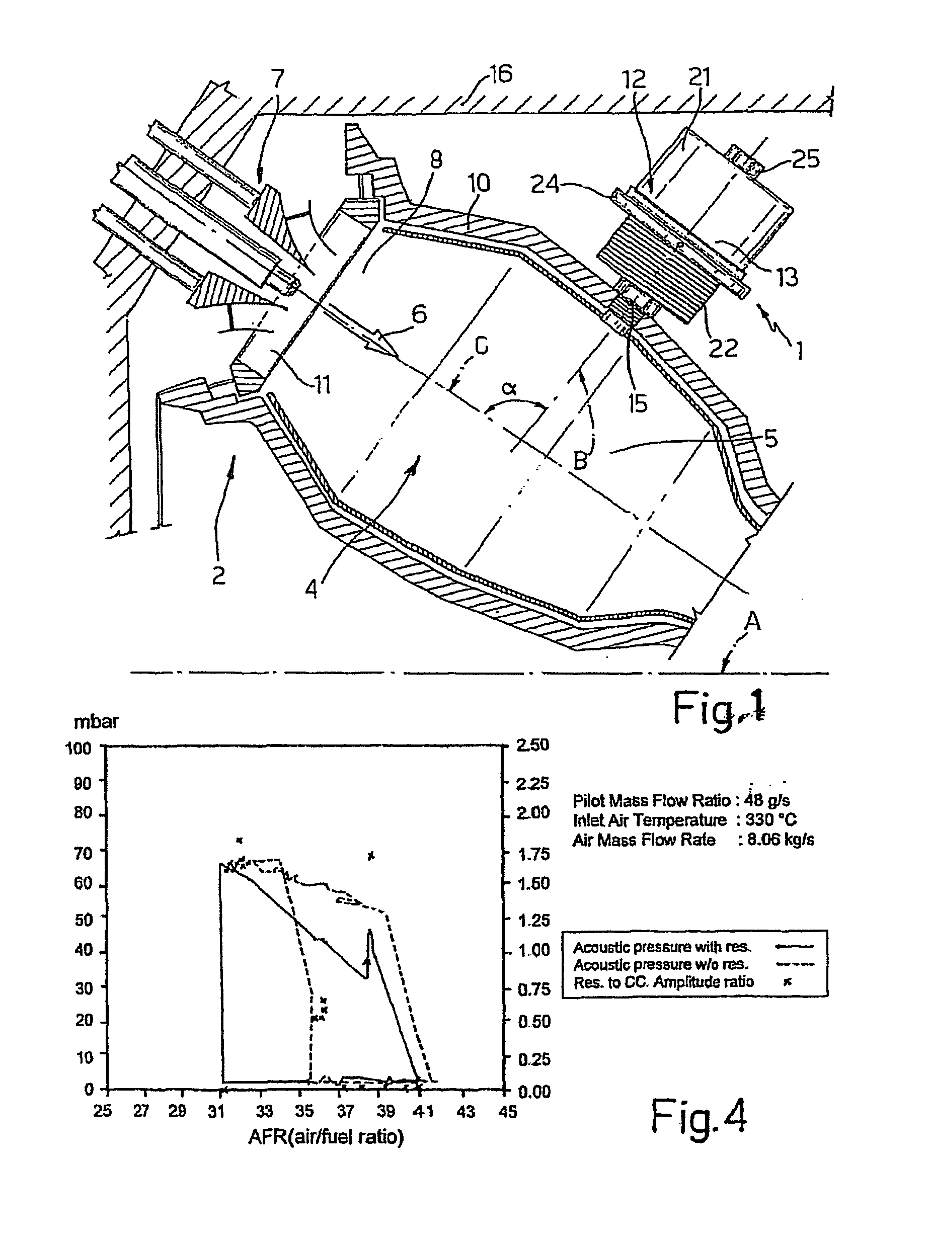
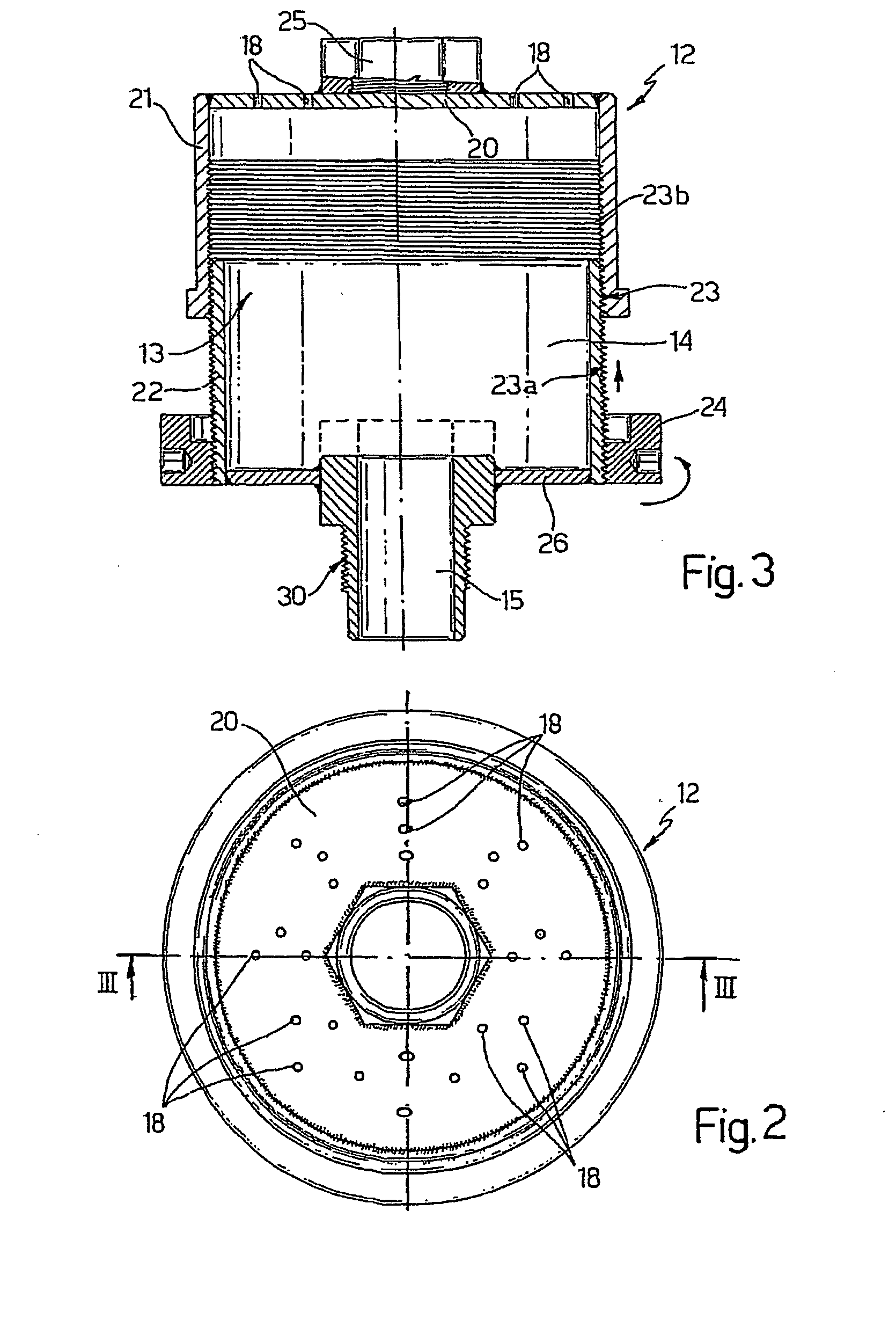
[0050]The damping system presented in the foregoing description, with reference to the annexed plate of drawings was tested in an experimental annular combustor manufactured by the present applicant, where a number of resonators were installed in conformance with the drawing of FIG. 3, said resonators being distributed along the circumference of the combustion chamber in the positions indicated in FIG. 1. More in particular, the annular combustor was connected to an existing (40-MWth) boiler and was made up of the following components;[0051]a combustion chamber of a commercially available AEN / SIE GT;[0052]twenty-four AEN / SIE hybrid burners;[0053]a natural-gas (NG) supply system for operating in diffusion, premixing, and pilot modes;[0054]an air supply from the fan of the boiler provided with a pre-heater for pre-heating up to 350° C.; and[0055]a chimney (the same as that of the boiler).

[0056]The instrumentation used comprised:[0057]a meter for measuring the flow, pressure, and tempe...


PUM


Abstract

A system for damping thermo-acoustic instability in a combustor device for a gas turbine, the combustor device including at least one combustion chamber, in particular of an annular type, and at least one burner associated to the combustion chamber and mounted in a position corresponding to a front portion set upstream of the combustion chamber; the damping system including at least one Helmholtz resonator including a casing defining inside it a pre-set volume and a neck for hydraulic connection between the pre-set volume and the combustion chamber, the neck being connected to one side of the combustion chamber at a distance from the front upstream portion thereof provided with the at least one burner. The casing of the resonator includes structure which varies the pre-set volume within a pre-set range and structure which delivers a cooling fluid.

Description

TECHNICAL FIELD[0001]The present invention relates to a system for damping thermo-acoustic instability in a combustor device comprising at least one combustion chamber and at least one burner associated to said combustion chamber and designed to serve a gas turbine, which uses passive damping means, in particular Helmholtz resonators.BACKGROUND ART[0002]It is known that, to achieve increasingly higher efficiency in gas turbines, in particular latest-generation ones, it is necessary both to use increasingly higher start-of-expansion temperatures and to obtain, in the most efficient way possible, an optimal homogeneity of temperature on the blades. Said results can be achieved and, in actual fact, are currently achieved, using combustion chambers with annular geometry.[0003]The aforementioned combustion chambers enable excellent performance both as regards efficiency of combustion and as regards the limitation of pollutant emissions and the high density of thermal yield (MWth / m3). How...

Claims


Application Information

Patent Timeline
Patent Type & Authority Applications(United States)
IPC IPC(8): F23M13/00F23R3/50F23M20/00
CPCF23R3/50F23M20/005F23M20/00F23R2900/00014
Inventor POLLAROLO, GIACOMO
Owner ANSALDO ENERGIA SPA
Why Eureka
Try Eureka