
Wet type friction plate
a friction plate and wet technology, applied in the direction of fluid actuated clutches, clutches, non-mechanical actuated clutches, etc., can solve the problem of increasing achieve the effect of reducing the drag torque during idle rotation, and reducing the migration of excessive lubricating oil
- Summary
- Abstract
- Description
- Claims
- Application Information
AI Technical Summary
Benefits of technology
Problems solved by technology
Method used
Image


Examples
first embodiment
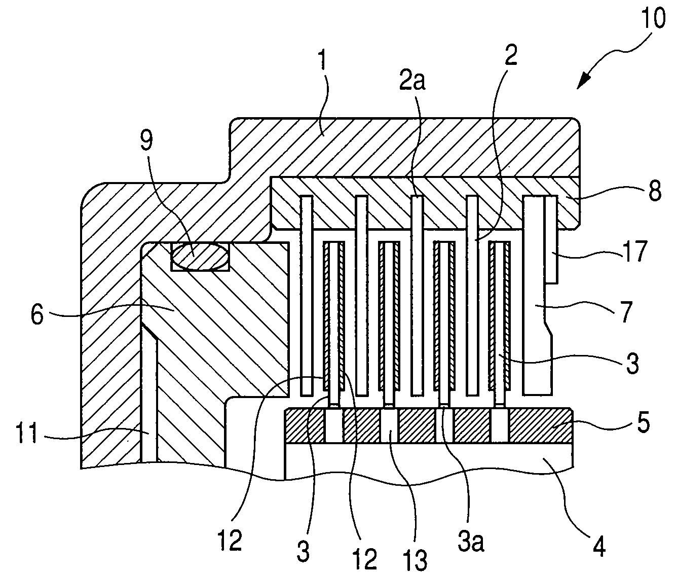
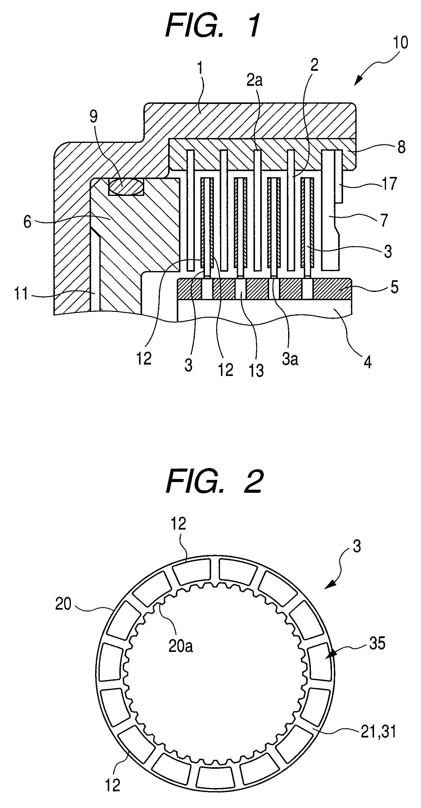
[0034]FIG. 3 is a partial sectional view of a friction plate 3 along a circumferential direction, showing a first embodiment of the present invention. The friction plate 3 is formed by securing a plurality of friction material segments 12 to the core plate 20 by an adhesive or the like.
[0035]A groove 21 extending through an inner diameter side to an outer diameter side is provided between the friction material segments 12, and a recessed portion facing toward the core plate 20 is formed on a circumferential side surface 22 of the friction material segment 12 defining the groove 21.
[0036]The recessed portion is formed as a tapered portion 23 inclined from the side surface 22 toward the inside of the friction material segment 12. As can be seen from FIG. 3, a circumferential width of the groove 21 at the position of the core plate 20 is greater than a circumferential width of an opening portion 26 of the groove 21. Two tapered portions of the adjacent friction material segments are op...
second embodiment
[0038]FIG. 4 is a partial sectional view of a friction plate 3 along a circumferential direction, showing a second embodiment of the present invention. Similar to the first embodiment, the friction plate 3 is formed by securing a plurality of friction material segments 12 to the core plate 20 by an adhesive or the like.
[0039]Also in the second embodiment, a groove 31 extending through an inner diameter side to an outer diameter side is provided between the friction material segments 12, and a recessed portion facing toward the core plate 20 is formed on a circumferential side surface 22 of the friction material segment 12 defining the groove 31.
[0040]In the second embodiment, the recessed portion is formed as a recess 28 cut from the side surface 22 toward the inside of the friction material segment 12. As can be seen from FIG. 4, a circumferential width of the groove 31 at the position of the core plate 20 is greater than a circumferential width of an opening portion 26 of the groo...
PUM
 Abstract
Description
Claims
Application Information