Plasma display panel

a technology of display panel and plasma, which is applied in the direction of discharge tube luminescnet screen, electric discharge tube, gas-filled discharge tube, etc., can solve the problems of reducing the pitch of the cell and frequent misalignment between the barrier rib and the electrode, so as to prevent (or reduce) the occurrence of non-uniform discharge. , the effect of increasing reliability

Inactive Publication Date: 2008-10-02
SAMSUNG SDI CO LTD
View PDF3 Cites 0 Cited by
  • Summary
  • Abstract
  • Description
  • Claims
  • Application Information

AI Technical Summary

Benefits of technology

[0013]An aspect of the present invention is directed to providing a plasma display panel having inc...

Problems solved by technology

However, as the number of discharge regions is increased in order to improve image quality, a cell pitc...

Method used


Image

  • Plasma display panel
  • Plasma display panel
  • Plasma display panel

Examples


Embodiment Construction

[0031]The present invention will now be described more fully with reference to the accompanying drawings in which exemplary embodiments of the invention are shown.

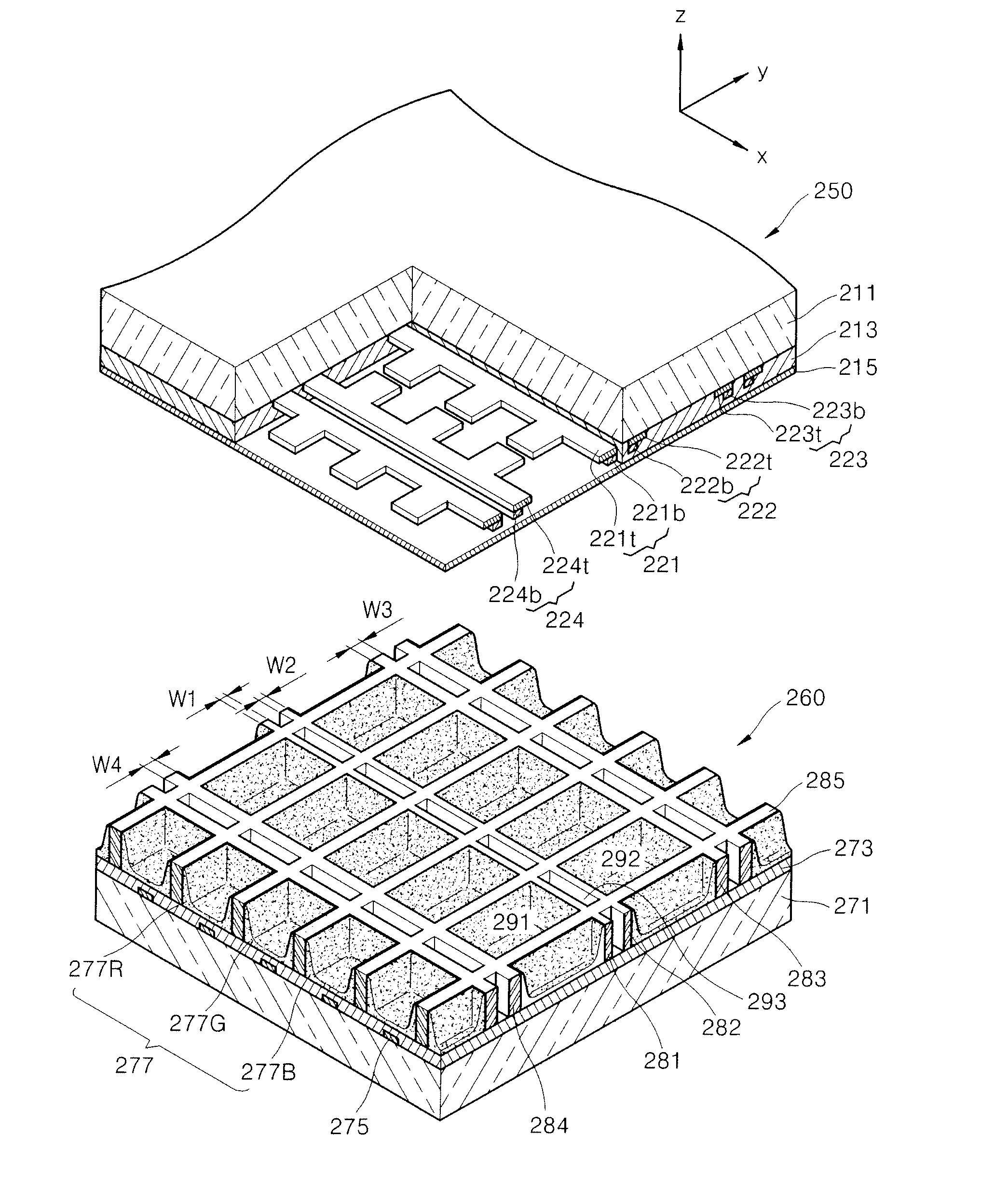
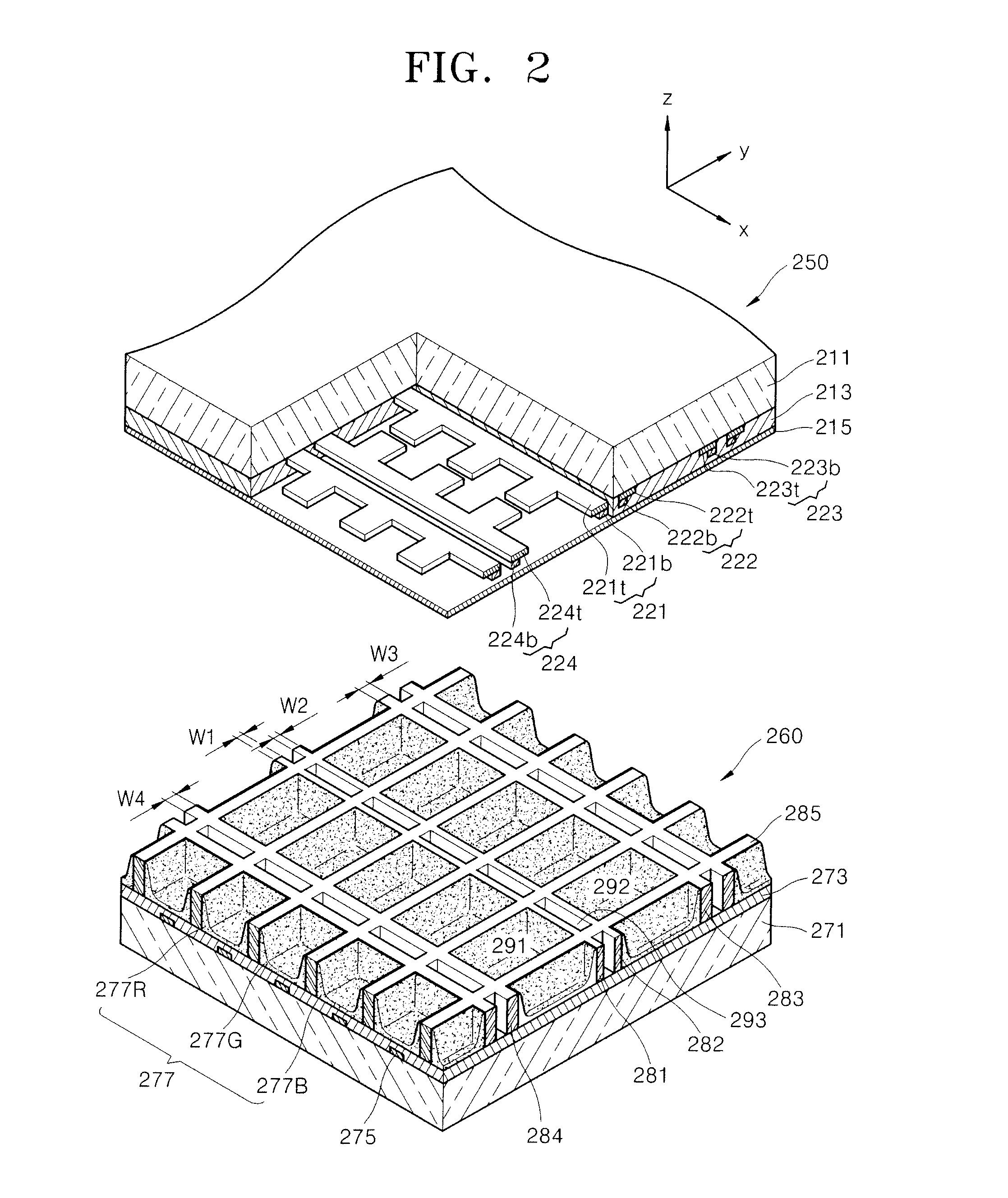
[0032]FIG. 2 is a partial cutaway exploded perspective view of a plasma display panel (PDP) according to an embodiment of the present invention.

[0033]Referring to FIG. 2, the plasma display panel includes an upper panel 250 and a lower panel 260.

[0034]The upper panel 250 includes a first substrate 211, an upper dielectric layer 213, a protective layer 215, and a plurality of discharge electrodes.

[0035]The first substrate 211 is formed of a material having a high optical transmittance, for example, glass or soda lime glass. The first substrate 211 can be colored to increase bright room contrast by reducing external light reflection.

[0036]A plurality of discharge electrodes are formed on the first substrate 211.

[0037]The discharge electrodes include a first electrode 221, a second electrode 222, a third electrode 223, and a ...


PUM


Abstract

A plasma display panel includes: a first substrate and a second substrate facing the first substrate, the first and second substrates defining a discharge space therebetween; and barrier ribs between the first and second substrates and defining non-discharge and discharge regions at the discharge space. The barrier ribs include: first ribs and second ribs adjacent the first ribs, the first and second ribs defining the non-discharge regions; third ribs adjacent the second ribs, the second and third ribs defining first discharge regions of the discharge regions, the first regions being adjacent the non-discharge regions, and the third ribs having a width different from that of the second ribs; and fourth ribs adjacent the first ribs, the first and fourth ribs defining second discharge regions of the discharge regions, the second regions being adjacent the non-discharge regions, and the fourth ribs having a width different from that of the first ribs.

Description

CROSS-REFERENCE TO RELATED PATENT APPLICATION[0001]This application claims priority to and the benefit of Korean Patent Application No. 10-2007-0030367, filed on Mar. 28, 2007, in the Korean Intellectual Property Office, the entire content of which is incorporated herein by reference.BACKGROUND OF THE INVENTION[0002]1. Field of the Invention[0003]The present invention relates to a plasma display panel.[0004]2. Description of the Related Art[0005]In a conventional plasma display panel, a barrier rib structure formed between upper and lower panels defines a plurality of discharge cells, phosphor layers are coated on walls of the barrier rib structure, and each of the discharge cells is filled with a main discharge gas such as neon (Ne) gas, helium (He) gas, or a mixture gas of Ne gas and He gas, and an inert gas that contains a small amount of xenon (Xe) gas. When a high frequency voltage is applied to the plasma display panel, vacuum ultraviolet rays are generated from the inert gas,...

Claims


Application Information

Patent Timeline
IPC IPC(8): H01J1/62
CPCH01J11/12H01J11/36H01J2211/245H01J2211/361
Inventor SONG, JUNG-SUK
Owner SAMSUNG SDI CO LTD
Why Eureka
Try Eureka