Light fixtures and lighting devices

a technology of light fixtures and lighting devices, applied in the field of light fixtures, can solve the problems of difficult to achieve these challenging design criteria with solid-state light emitters, and the challenge of managing extreme luminance, and achieve the effect of carefully balanced radiative coupling and luminances

Active Publication Date: 2008-11-13
IDEAL IND LIGHTING LLC
View PDF24 Cites 164 Cited by
  • Summary
  • Abstract
  • Description
  • Claims
  • Application Information

AI Technical Summary

Benefits of technology

[0012]In accordance with the present inventive subject matter, there are provided light fixtures which satisfy these needs, and which further enable new aesthetic possibilities. In addition, in accordance with the present inventive subject matter, there are provided light fixtures (e.g., troffers) for solid state light emitters wh

Problems solved by technology

It would be difficult to achieve these challenging design criteria with solid state light emitters.
It was also recognized that it would be a c

Method used


Image

  • Light fixtures and lighting devices
  • Light fixtures and lighting devices
  • Light fixtures and lighting devices

Examples


first embodiment

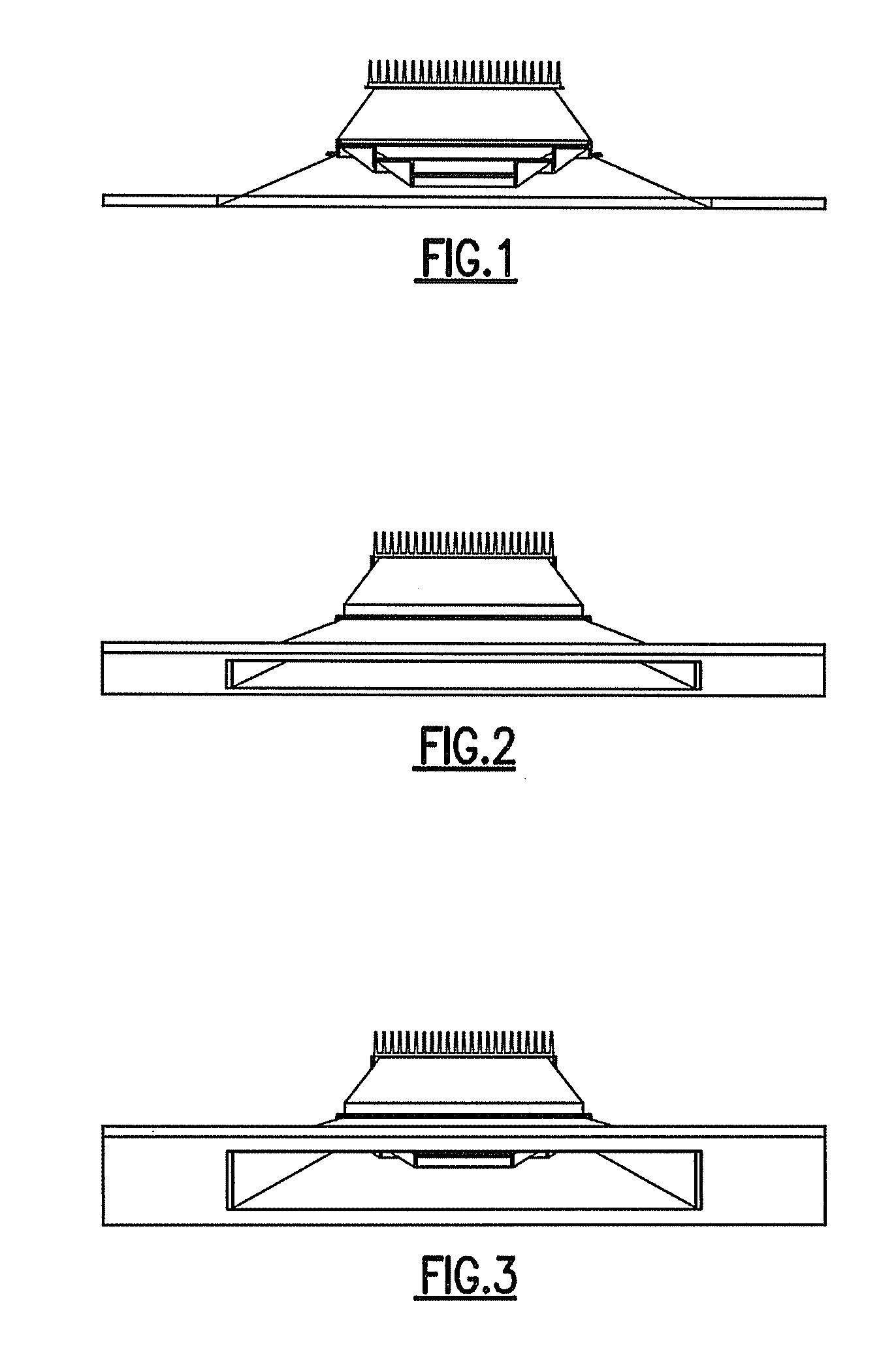
[0081]FIG. 1 is a cross-sectional view of a luminaire according to the present inventive subject matter. The location of the elements of the center baffling system create optimized distribution, appearance, and brightness control.

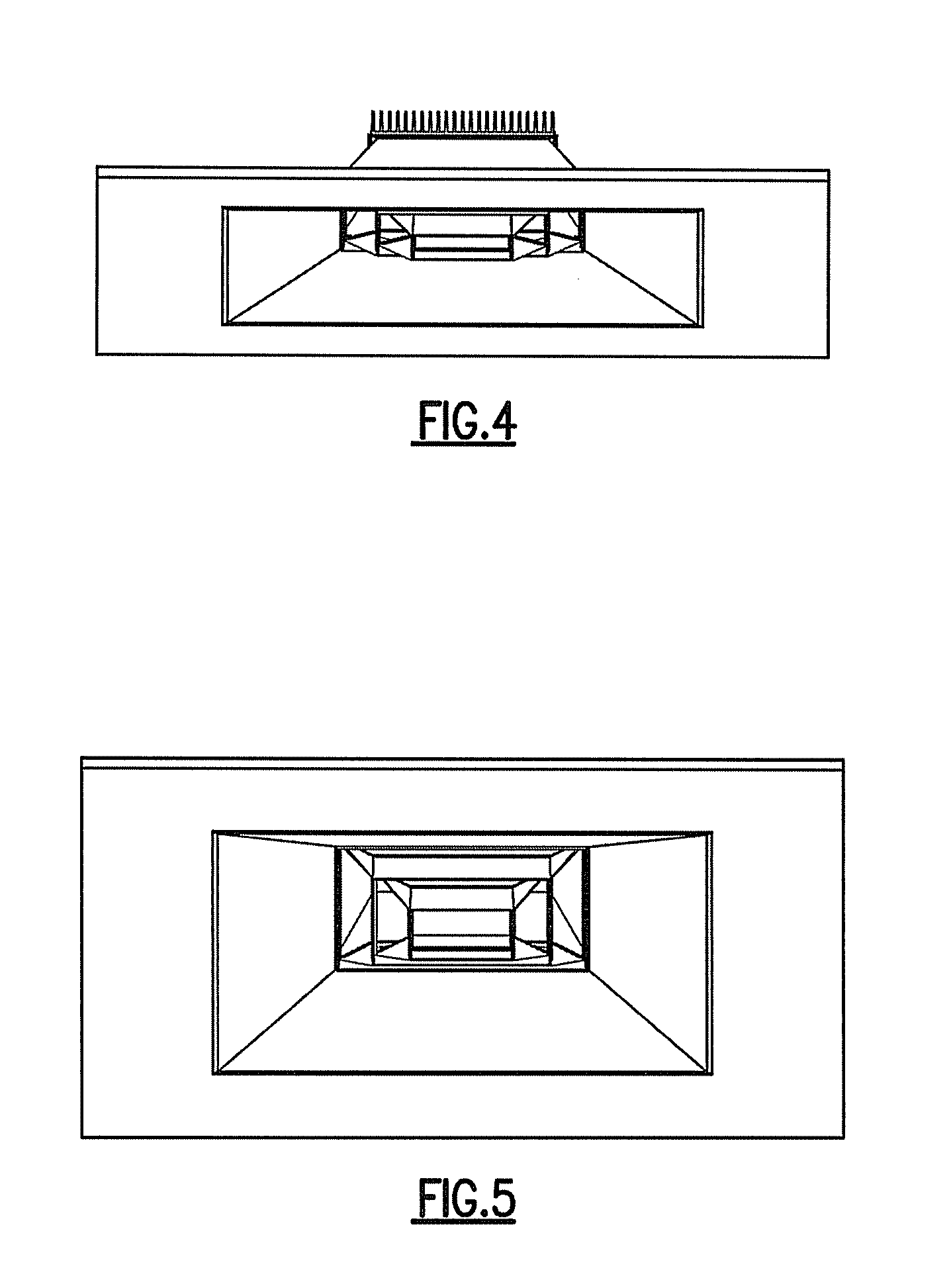
[0082]FIGS. 2-6 depict the troffer of FIG. 1 at various angles.

[0083]FIG. 2 depicts a high angle view. At this viewing angle, the occupant is typically more than 20 feet away from the light. In a large room, the majority of luminaires will have this appearance. If a luminaire is too bright at this angle, it can cause discomfort or cause veiling reflections in computers. It can also create a busy ceiling appearance. To avoid these problems, the luminous elements of the baffling system are mechanically shielded from view. The side reflectors are the only luminous elements visible at this angle. These are illuminated by the baffle system with an average luminance that is significantly less than the baffles. The luminance gradient is the greatest next to the ba...

second embodiment

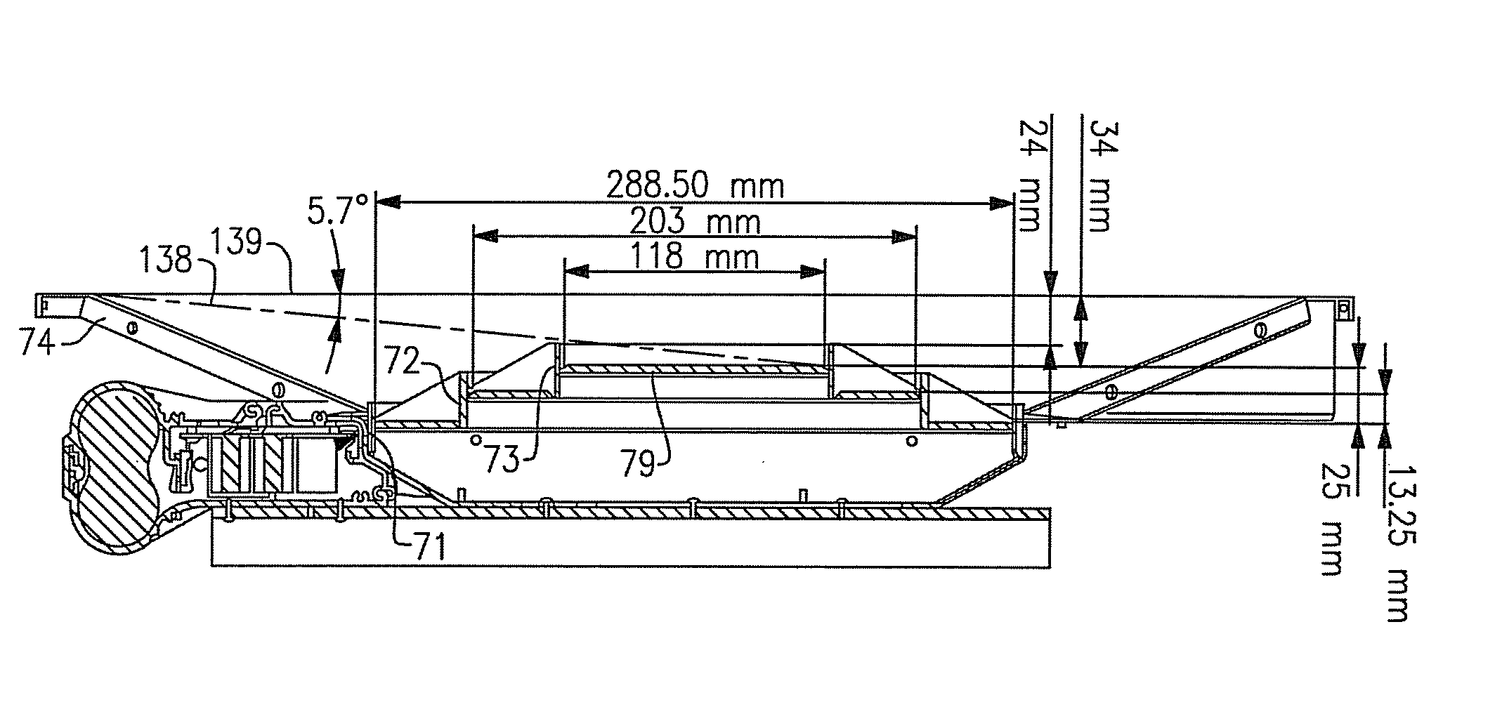
[0094]Referring again to FIG. 7, the second embodiment includes a lighting device 83. The lighting device 83 comprises a circuit board 121, a plurality of solid state light emitters 122 (in this embodiment, the solid state light emitters are LEDs) and circuitry for delivering desired current to each of the LEDs 122. Light emitted from the lighting device 83 travels in all directions, but in bulk, the emitted light travels downward, i.e., through the fourth plane 92, then through the first plane 80, then through the second plane 81, then through the third plane 82 and then through the plane 99 (referred to later as the “viewer plane”).

[0095]Referring to FIG. 8, it can be seen that all of the LEDs 122 are located entirely within planes 117, 118, 119, 120 which extend through the outer periphery of the inner baffle structure 73 perpendicular to the first plane 80 (i.e., the planes 117-120 extend perpendicularly into and out of the plane of the drawing page).

[0096]Persons of skill in th...


PUM


Abstract

There is provided a light fixture comprising a baffle system and a side reflector, the baffle system comprising at least an outer baffle structure and an inner baffle structure. Also, there is provided a light fixture which comprises at least two recessed concentric square elements, triangular connecting elements and lenses which are recessed from the faces of each of the square elements. In some embodiments, the lighting device comprises at least one solid state light emitter. In some embodiments, the light fixture further comprises at least one lens positioned between at least two respective baffle elements.

Description

CROSS-REFERENCE TO RELATED APPLICATIONS[0001]This application claims the benefit of U.S. Provisional Patent Application No. 60 / 916,407, filed May 7, 2007, the entirety of which is incorporated herein by reference.[0002]This application claims the benefit of U.S. Provisional Patent Application No. 61 / 029,068, filed Feb. 15, 2008, the entirety of which is incorporated herein by reference.[0003]This application claims the benefit of U.S. Provisional Patent Application No. 61 / 037,366, filed Mar. 18, 2008, the entirety of which is incorporated herein by reference.FIELD OF THE INVENTIVE SUBJECT MATTER[0004]The present inventive subject matter relates to a light fixture. In some aspects, the present inventive subject matter relates to a light fixture for use with solid state light emitters, e.g., light emitting diodes (LEDs).BACKGROUND[0005]A large proportion (some estimates are as high as twenty-five percent) of the electricity generated in the United States each year goes to lighting. Ac...

Claims


Application Information

Patent Timeline
IPC IPC(8): F21V7/00
CPCF21S8/02F21V11/02F21V29/70F21Y2101/02F21K9/58F21V29/004F21Y2115/10F21V29/763F21V1/02F21V23/00F21V15/01
Inventor TROTT, GARY DAVIDPICKARD, PAUL KENNETH
Owner IDEAL IND LIGHTING LLC
Why Eureka
Try Eureka