Optimum power management of system on chip based on tiered states of operation

US20080282101A1Active Publication Date: 2008-11-13GAINSPAN

Image

  • Optimum power management of system on chip based on tiered states of operation
  • Optimum power management of system on chip based on tiered states of operation
  • Optimum power management of system on chip based on tiered states of operation

Examples


Embodiment Construction

[0025]Optimum power management of a system on chip based on tiered states of operation is disclosed. In the following description, for purposes of explanation, numerous specific details are set forth in order to provide a thorough understanding of the various embodiments. It will be evident, however, to one skilled in the art that the various embodiments may be practiced without these specific details.

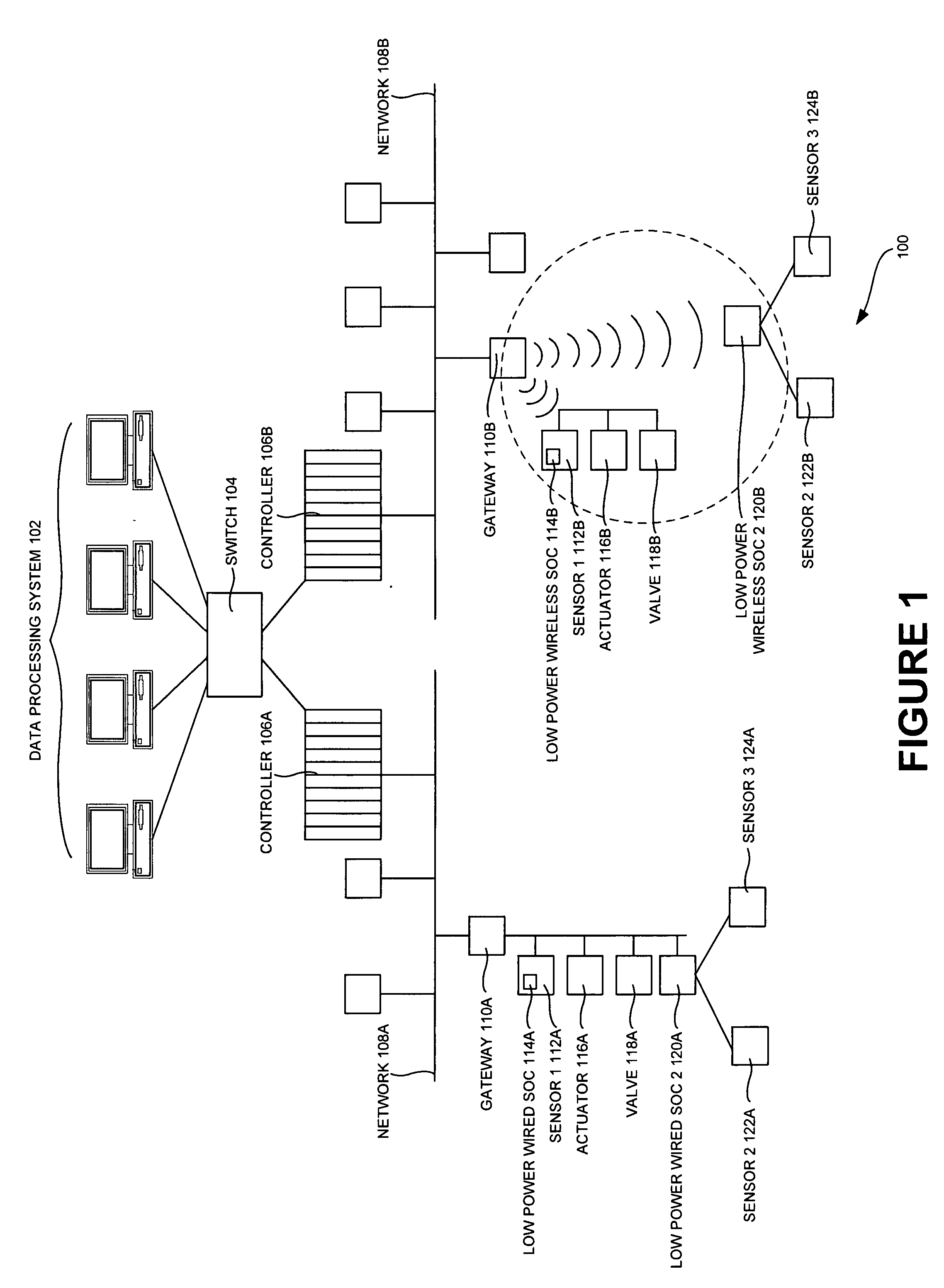
[0026]In one embodiment, a system on chip (e.g., a low power wired / wireless SOC 114 and / or a low power wired / wireless SOC 120 of FIG. 1) includes a hardware module including one or more of a microcontroller, a microprocessor, a DSP core, a memory, a timing source, a peripheral, and an external interface to have a real time counter module (e.g., a RTC module 502 of FIG. 5) isolated from the rest of the hardware module (e.g., the rest of SOC 504) using a plurality of voltage level shifting cells and / or a plurality of voltage island cells (e.g., an isolation logic 506). Also, the system o...


PUM


Abstract

Optimum power management of system on chip based on tiered states of operation is disclosed. In one embodiment, a system on chip includes a hardware module including one or more of a microcontroller, a microprocessor, a DSP core, a memory, a timing source, a peripheral, and an external interface to have a real time counter module of the peripheral isolated from a rest of the hardware module using a plurality of voltage level shifting cells and / or a plurality of voltage island cells. Also, the system on chip includes a software module associated with the real time counter module to generate one or more control signals to one or more devices external to the system on chip during a sleep mode of the system on chip.

Description

FIELD OF TECHNOLOGY[0001]This disclosure relates generally to technical fields of system on chip and, in one embodiment, to a system and / or method of optimum power management of system on chip based on tiered states of operation, comprising controlling the clock and other components that are enabled during certain states of the system on chip.BACKGROUND[0002]A system on chip may have all components of a computer and / or other electronic system into a single integrated circuit chip. The system on chip may contain any of digital, analog, and mixed-signal functions (e.g., as well as a radio-frequency function) all on one chip. The system on chip may have a microcontroller, a microprocessor, a DSP core, a memory block, a timing source, a peripheral, an external interface, and / or a power management circuit. The various hardware parts of the system on chip may be connected by buses (e.g., an AMBA bus, an APB, etc.). The system on chip may also include a number of software modules embedded ...

Claims


Application Information

Patent Timeline
13 Nov 2008
Publication
US20080282101A1
IPC
G06F1/32
CPC
G06F1/3287; Y02B60/32; G06F1/3243; Y02B60/1282; G06F1/3237; Y02B60/1278; G06F1/3203; Y02B60/1239
Inventors
ADAMS, LEWIS