Managing Housekeeping Operations in Flash Memory

a flash memory and housekeeping technology, applied in the direction of memory architecture accessing/allocation, instruments, computing, etc., can solve the problems of storage level shifting, less than optimal wear leveling, frequent compaction and/or garbage collection of reserved blocks, etc., to slow down the rate of data transfer, the performance of the memory system is adversely affected

a flash memory and housekeeping technology, applied in the direction of memory architecture accessing/allocation, instruments, computing, etc., can solve the problems of storage level shifting, less than optimal wear leveling, frequent compaction and/or garbage collection of reserved blocks, etc., to slow down the rate of data transfer, the performance of the memory system is adversely affected

US20080294813A1Inactive Publication Date: 2008-11-27SANDISK TECH LLC

Image

  • Managing Housekeeping Operations in Flash Memory
  • Managing Housekeeping Operations in Flash Memory
  • Managing Housekeeping Operations in Flash Memory

Examples


Embodiment Construction

Memory Architectures and Their Operation

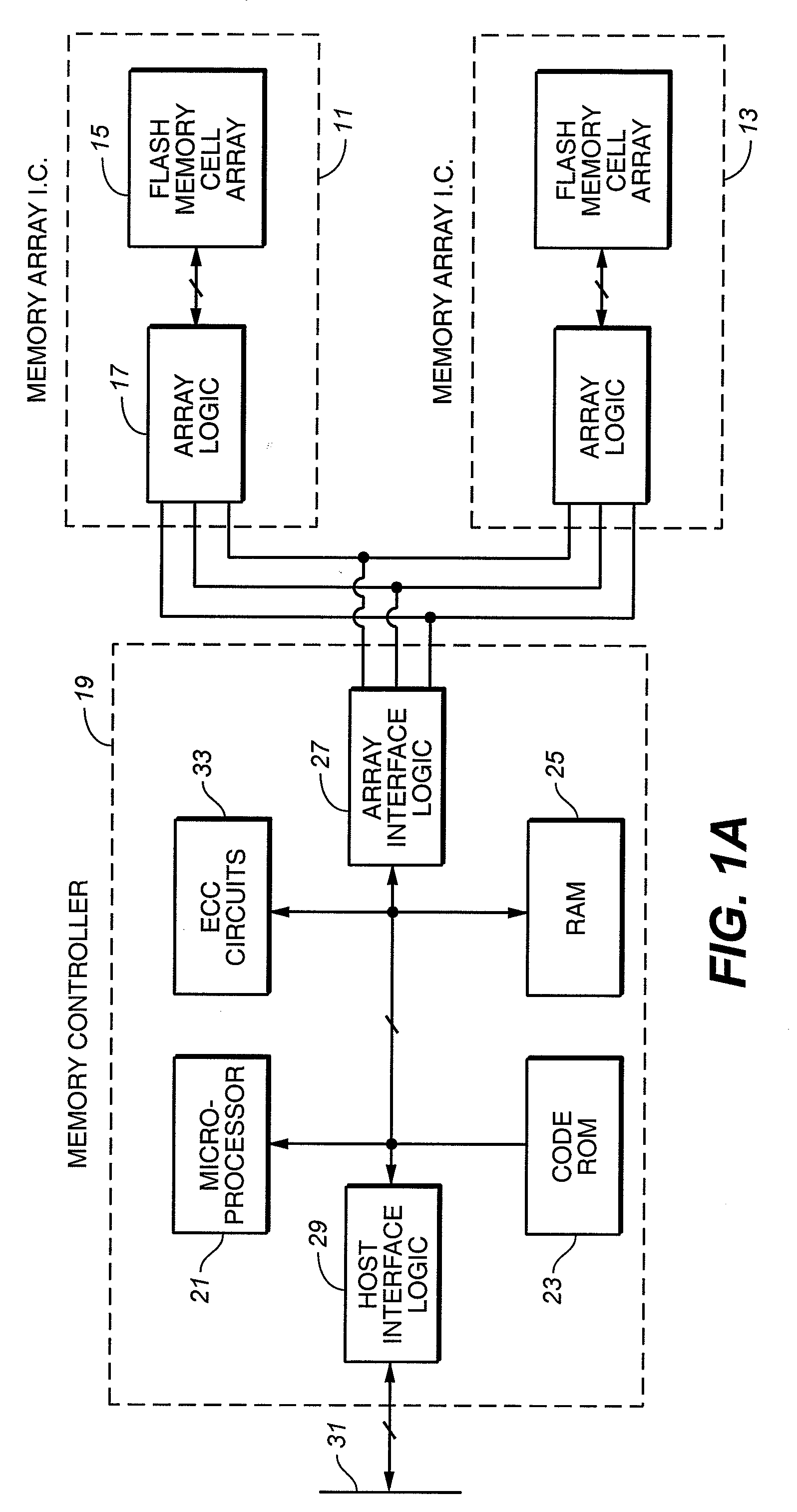
[0039]Referring initially to FIG. 1A, a flash memory includes a memory cell array and a controller. In the example shown, two integrated circuit devices (chips) 11 and 13 include an array 15 of memory cells and various logic circuits 17. The logic circuits 17 interface with a controller 19 on a separate chip through data, command and status circuits, and also provide addressing, data transfer and sensing, and other support to the array 13. A number of memory array chips can be from one to many, depending upon the storage capacity provided. The controller and part or the entire array can alternatively be combined onto a single integrated circuit chip but this is currently not an economical alternative. A flash memory device that relies on the host to provide the controller function contains little more than the memory integrated circuit devices 11 and 13.

[0040]A typical controller 19 includes a microprocessor 21, a read-only-memory (ROM) 23 pri...


PUM


Abstract

A flash re-programmable, non-volatile memory system is operated to disable foreground execution of housekeeping operations, such as wear leveling and data scrub, in the when operation of the host would be excessively slowed as a result. One or more characteristics of patterns of activity of the host are monitored by the memory system in order to determine when housekeeping operations may be performed without significantly degrading the performance of the memory system, particularly during writing of data from the host into the memory.

Description

CROSS REFERENCE TO RELATED APPLICATION[0001]This application is related to an application being filed concurrently herewith by Sergey Gorobets, entitled “Flash Memory System with Management of Housekeeping Operations” which application is incorporated herein in its entirety by this reference.GENERAL BACKGROUND[0002]This invention relates generally to the operation of non-volatile flash memory systems, and, more specifically, to techniques of carrying out housekeeping operations, such as wear leveling and data scrub, in such memory systems.[0003]There are many commercially successful non-volatile memory products being used today, particularly in the form of small form factor removable cards or embedded modules, which employ an array of flash EEPROM (Electrically Erasable and Programmable Read Only Memory) cells formed on one or more integrated circuit chips. A memory controller, usually but not necessarily on a separate integrated circuit chip, is included in the memory system to int...

Claims


Application Information

Patent Timeline
27 Nov 2008
Publication
US20080294813A1
IPC
G06F13/12
CPC
G06F12/0246; G06F2212/1016; G06F2212/7205
Inventors
GOROBETS, SERGEY ANATOLIEVICH