Arrangement for Affixing an Expandable Packer in a Hole

Inactive Publication Date: 2008-12-11
ATLAS COPCO CRAELIUS
View PDF15 Cites 5 Cited by
  • Summary
  • Abstract
  • Description
  • Claims
  • Application Information

AI Technical Summary

Benefits of technology

[0012]According to a further beneficial feature of the invention, the cylinder includes a separate part, which is mounted at least partially on the main body. This provides advantages from a manufacturing aspect.
[0013]The piston may also be provided with a return spring to facilitate and to ensure return of the piston to its starting position when it is no longer influenced by the pressurized medium.
[0014]Another beneficial feature of the inventive arrangement is that it has maximum measurements which enable it to be inserted totally in said hole. As earlier mentioned, this pro

Problems solved by technology

Work on and in rock walls often results in problems involving moisture and water that penetrates through cracks in the rock, which often requires the cracks to be sealed.
However, these sealants are unable to penetrate out into the actual cracks to any appreciable extent, wherewith the leakage problems remain in many instances.
Consequently, this type of packer is expensive, since it is designed for one-time-use only.
The disadvantage of this type of packer is that it can only be used in the close vicinity of the hole opening, since the tool is relatively unwieldy and space-demanding.
Because the packer cannot be inserte

Method used


Image

  • Arrangement for Affixing an Expandable Packer in a Hole
  • Arrangement for Affixing an Expandable Packer in a Hole
  • Arrangement for Affixing an Expandable Packer in a Hole

Examples


first embodiment

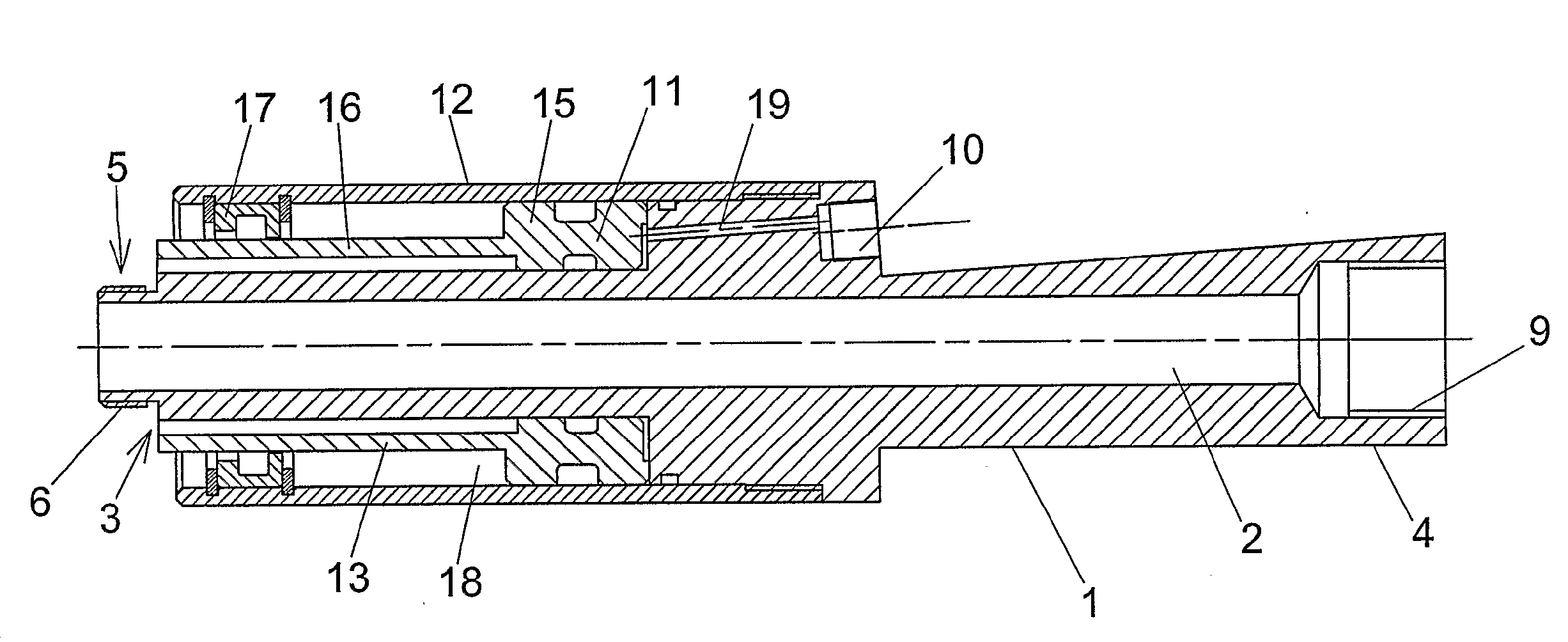
[0034]The embodiment of the inventive arrangement shown in FIG. 5 includes the same fundamental components as the first embodiment shown in FIG. 1. The arrangement includes an elongate main body 1 through which there extends a through-passing aperture 2. The main body has a front end 3, which faces in towards the hole in use, for affixing a packer 32 in the hole, and an opposite rear end 4. The rear end 4 of the main body 1 carries means for connection to means for supplying filler or sealant. The nature of these connecting means has already been discussed in connection with FIG. 1, although it will be understood that other types of connecting means are conceivable. The figure shows that the arrangement is connected to a supply means through the medium of a tubular part 30, as will be described hereinafter.

[0035]The main body 1 also includes pressure connecting means 10 for connection to a pressure medium source in a manner corresponding to that already described with reference to F...

second embodiment

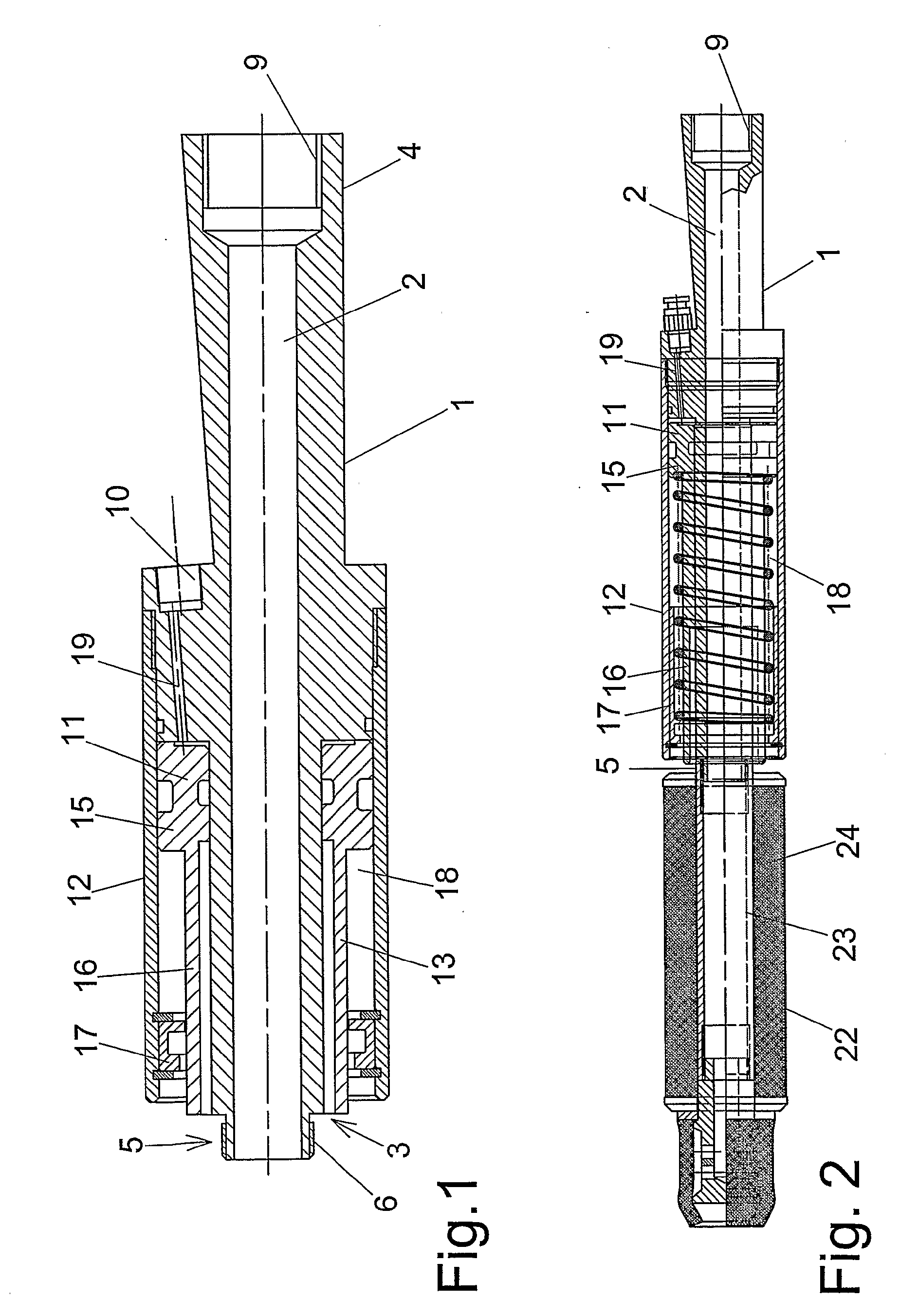
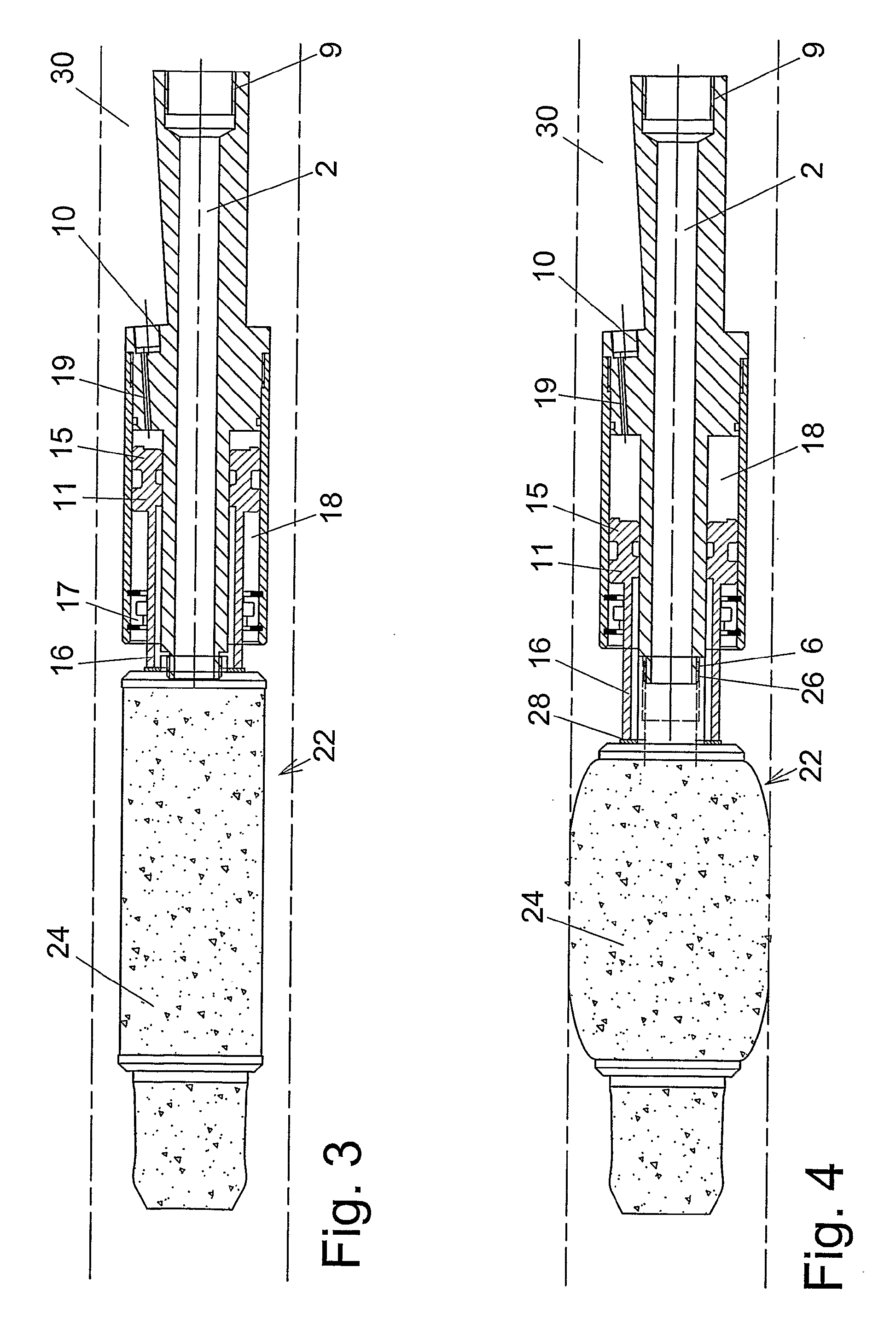
[0037]This second embodiment of the arrangement is designed so that a tubular part 30 can be inserted in the through-penetrating aperture 2 in the main body 1. This tubular part constitutes an extension of a tubular part seated within the packer 32 and normally used to deliver filler to the front end of the packer. In turn, the packer is seated firmly on the tubular part 30. The device for affixing the packer is designed so that the tubular part, with the packer 32, is rotatable in the through-penetrating aperture 2. This is achieved by providing the arrangement with appropriate bearings and bushes. The arrangement is thus not affixed to the packer but is, nevertheless, fixed in relation to the same in an axial direction through the medium of the tubular part 30, which functions as a shaft. As the packer 32 expands, the front part 16 of the piston is moved forwards out of the cylinder 12 and towards the rearmost part 31 of the packer, with the aid of supplied pressure medium, so tha...


PUM


Abstract

The present invention relates to an arrangement for affixing an expandable packer 22, 32 in a hole 30, wherein the arrangement includes a piston-and-cylinder device 11, 12 with which the piston can be caused to move in the cylinder with the aid of a pressurized medium. Expansion of the packer is effected with the aid of the movement of the piston 11, by transferring the force generated by piston movement to an expandable part 24, 34 of the packer 22, 32 so that said part will expand. Expansion of the packer results in the packer being firmly affixed in the hole by means of friction. The arrangement also includes an elongate main body 1 that has a through-penetrating aperture extending in the longitudinal direction of the body. The main body 1 has a front end 3, which faces inwardly of the hole when fastening the packer and towards the packer. The body includes a rear end 4 which carries means 9 for connection to a filler supply means, wherewith filler is delivered to the hole via the through-penetrating aperture 2 and via the packer 22, 32 subsequent to having affixed the packer in the hole. At least a part of the main body 1 is formed as a piston rod 16 on which and along which the piston 11 can move. The arrangement also includes pressure connection means 10 for connection to said pressurized medium, and a connection 19 between said pressure connection means and the piston 11.

Description

TECHNICAL FIELD OF THE INVENTION[0001]The present invention relates to an arrangement for affixing an expandable packer in a hole in a rock wall, preferably a pre-drilled hole. The arrangement includes a piston-cylinder device with which the piston can be caused to move in the cylinder with the aid of a pressurized medium, wherein expansion of the packer is effected with the aid of piston movement by virtue of transferring the force generated by said movement to an expandable part of the packer therewith causing the same to expand, wherewith expansion of the packer results in the packer being affixed in the hole by means of friction, as described in the preamble of claim 1.BACKGROUND OF THE INVENTION[0002]Work on and in rock walls often results in problems involving moisture and water that penetrates through cracks in the rock, which often requires the cracks to be sealed. Leakages also often occur in the vicinity of holes drilled with the intention of strengthening the rock wall, a...

Claims


Application Information

Patent Timeline
IPC IPC(8): E21B33/128E21D
CPCE21B33/1285
Inventor ERIKSSON, JANPETERSSON, STEN-AKE
Owner ATLAS COPCO CRAELIUS
Why Eureka
Try Eureka