In-line gasifier having a cooling jacket with pipework passing through the side of the pressure cladding

a gasifier and pressure cladding technology, which is applied in the direction of combustible gas production, lighting and heating apparatus, gasification of granular/pulverulent flues, etc., can solve the problems of limiting the nominal size of the cooling water pipe, unable to achieve total emptying for the purpose of avoiding freezing up, and unable to achieve total emptying. , to achieve the effect of reducing the mounting and maintenance effort, improving accessibility, and special quality assurance measures

Active Publication Date: 2013-02-14
SIEMENS ENERGY GLOBAL GMBH & CO KG
View PDF3 Cites 4 Cited by
  • Summary
  • Abstract
  • Description
  • Claims
  • Application Information

AI Technical Summary

Benefits of technology

[0011]The elimination of the cover bushing for the cooling pipes substantially reduces the mounting and maintenance effort when replacing the cooling jacket. Furthermore, all the welded seams can be tested and extensive special quality assurance measures are eliminated. Another advantage is the better accessibility for inspections of the gap between the cooling jacket and the pressure vessel.
[0012]In a particular embodiment, the individual pipe runs are joined at their lower ends to a connector bush (19), which forms a pressure-tight passage through the pressure cladding. This measure makes it possible to completely empty the cooling jacket, when it is out of service, whereby the risk of destruction from sub-zero temperatures is eliminated, or on the other hand it is possible to dispense with the expense of keeping it warm or the use of antifreeze agents.
[0013]In one particular embodiment, the lower ends of several parallel pipe runs are joined to a common distributor ring (6), which is arranged in the lower region of the cooling jacket (14) and which is joined to a connector bush (19) which forms a pressure-tight passage through the pressure cladding. In one particular embodiment, the upper ends of several parallel pipe runs are joined to a common collector ring, which is arranged in the upper region of the cooling jacket (13) and which is joined to a connector bush (20) which forms a pressure-tight passage through the pressure cladding below the cladding flange (2). The inventive measures permit the construction of gasifiers with a high capacity with a limited nominal size of cooling jacket pipes and a reduced number of connectors through the pressure vessel. In addition, they make it possible to increase the number of starts, pipe runs and turns. The limitation of the nominal size of pipe leads at the same time to a limitation in the pipe wall thickness, and hence an improvement in the heat transfer.

Problems solved by technology

The increasing number of coils for larger gasifier capacity requires more connectors, which it is either impossible or illogical to arrange on the head of the vessel because of space limitations.
Total emptying for the purpose of avoiding freezing up is not possible.
The nominal size of the cooling water pipes represents a further limiting factor in the dimensioning of the cooling jacket.
As the reaction space is enlarged, with the objective of raising the capacity, the heat exchange area increases, with the result that a larger quantity of water is required to dissipate the amount of heat.
An enlargement of the nominal size of the pipe diameter has the observable disadvantage that, on the one hand, the molten slag flows away less well at the tube wall and, on the other hand, the slag formation becomes less uniform, and overall becomes worse.
As the nominal size is increased, a lower percentage of the water volume participates in the direct heat exchange, which can also promote local overheating.
The cooling water cannot be completely removed by the usual measures, such as draining off or “blowing out” using compressed air, so that in winter it is necessary to keep the circuit, the vessel, or its surroundings frost-free when taken out of service.
A problem is that of designing an in-line gasifier with a liquid-cooled cooling jacket in such a way as to simplify the way the pressure vessel cover is mounted.

Method used


Image

  • In-line gasifier having a cooling jacket with pipework passing through the side of the pressure cladding
  • In-line gasifier having a cooling jacket with pipework passing through the side of the pressure cladding

Examples


Embodiment Construction

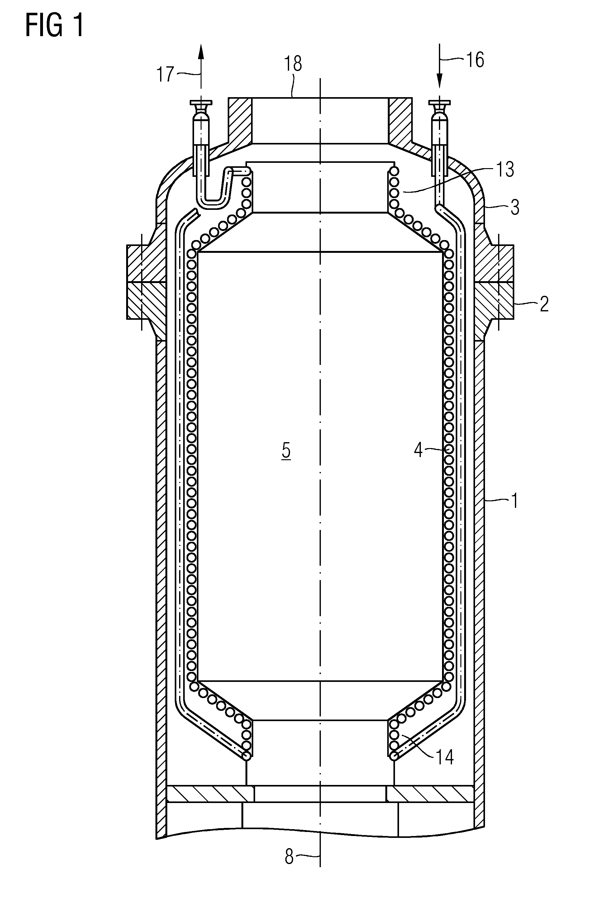
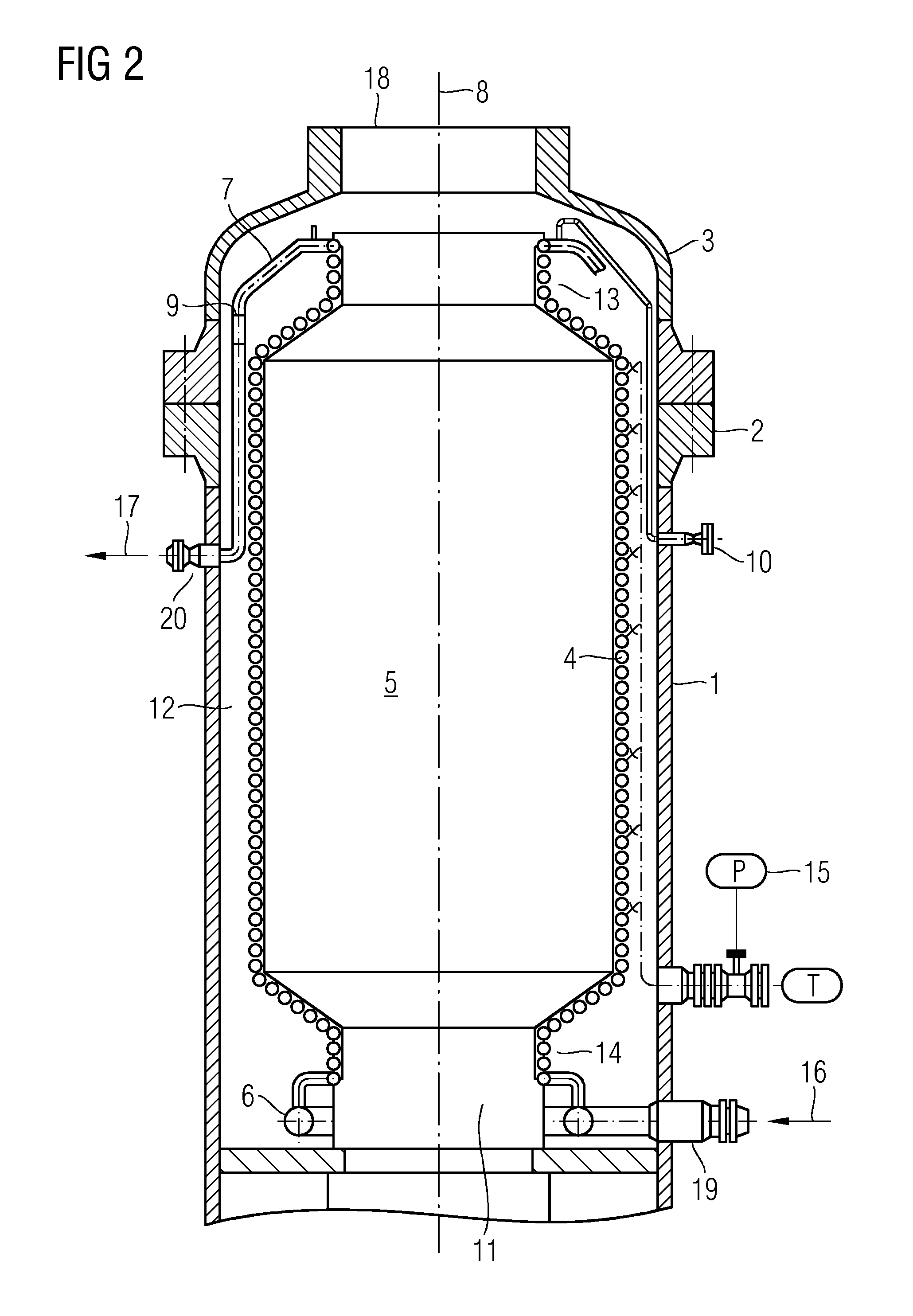
[0019]The reaction space (5) of a gasification reactor operating under a gasification pressure of up to 10 MPa (100 bar) is bounded by a cooling jacket (4), which is sheathed in a pressure cladding (1). At the head of the device is located the base of the gasification burner (18), through which are fed in the reaction media, fuel and gasification agents containing free oxygen. The gasified gas and the molten slag, which is formed from the fuel ash at the gasification temperature of between 1,200 and 1,900° C., are tapped off through the opening (11). Between the pressure cladding and the cooling jacket is the cooling jacket gap (12). The upper part (13) and lower part (14) of the cooling jacket are tapered.

[0020]The cooling water, which is heated in the cooling jacket, is fed away as hot water and is cooled, making use of its heat content, and fed back to the cooling jacket again as cooling water. The water pressure in the cooling jacket is kept a few tenths of an MPa (a few bar) ab...


PUM


Abstract

For an in-line gasifier having a liquid cooled cooling jacket it is proposed to lead the inlet connectors and the outlet connectors for the cooling liquid through the side of the cylindrical pressure vessel, below the mounting flange for the vessel cover. This achieves a simplification in the mounting of the pressure vessel cover. Particular embodiments concern the bringing together of the upper ends and of the lower ends of several pipe runs coiled in parallel, in each case into a collector pipe which has a connector bush for cooling water.

Description

CROSS REFERENCE TO RELATED APPLICATIONS[0001]This application claims priority of German application No. 10 2011 080838.8 DE filed Aug. 11, 2011. All of the applications are incorporated by reference herein in their entirety.FIELD OF INVENTION[0002]A reactor for gasifying carbon-containing slag-forming fuels, using a gasification agent containing free oxygen, in-line in the flow at pressures of up to 10 MPa, with simplified mounting of the pressure vessel cover is provided.BACKGROUND OF INVENTION[0003]For gasifiers for in-line gasification of slag-forming fuels, a known possibility is to delimit the reaction space by a multi-start spiral shaped coiled pipe diaphragm wall, also referred to as a cooling jacket. The cooling water which flows through the cooling jacket is fed in and out via connectors which are connected to the cover of the gasifier (FIG. 1). DE 202009012134 discloses an appropriate construction with four cooling water inlets and four cooling water outlets.[0004]The incr...

Claims


Application Information

Patent Timeline
Patent Type & Authority Applications(United States)
IPC IPC(8): F28D21/00
CPCC10J3/20C10J3/46C10J3/48C10J3/74C10J3/485C10J2300/0959C10J3/86C10J3/78C10J2300/093C10J2300/0956C10J3/76
Inventor DEGENKOLB, DIETMARHANNEMANN, FRANKHOPPE, HORSTJUST, TINO
Owner SIEMENS ENERGY GLOBAL GMBH & CO KG
Why Eureka
Try Eureka