Pipette tip adapter

a technology of air displacement and pipette, which is applied in the direction of laboratory glassware, laboratory glassware, chemistry apparatus and processes, etc., can solve the problems of cross contamination, heavy designs that require more power to operate effectively, and cross contamination of different types, so as to reduce mounting and ejection forces, reduce mounting forces, and reduce costs

Inactive Publication Date: 2018-05-03
AVIDIEN TECH
View PDF9 Cites 7 Cited by
  • Summary
  • Abstract
  • Description
  • Claims
  • Application Information

AI Technical Summary

Benefits of technology

[0010]Broadly stated, embodiments of the present invention address the drawbacks of the prior art by providing a pipette tip adapter whose purpose is to adapt commonly available low cost pipette tips to a multichannel air displacement pipettor in a way that reduces the mounting and ejection forces described above. Any universal pipette tip available in the marketplace can be assembled to the pipette tip adapter. End users of the related multichannel air displacement pipettor designed to accept the pipette tip adapter would install the assembly onto the pipettor. The pipette tip adapter reduces the forces required to mount and seal the tips to less than 10 lbs. Ejection forces are equally reduced.

Problems solved by technology

Cross contamination can occur when a first liquid sample aspirated into and then dispensed from a pipette tip leaves a residual amount of sample in the tip.
A subsequently aspirated sample mixes with the residual first sample and is thus contaminated.
This type of cross contamination can also occur through residual sample on the exterior of the pipette tip.
This leads to heavier designs that require more power to operate effectively.
In addition to these design issues, the safety of the user is also a significant concern when such high forces are present.
The high forces required to attach all of the tips in the rack often causes the tip rack to bow in the center of the array, resulting in poor sealing and attachment of centrally located tips.
This, in turn, increases the cost of the racks and therefore the cost to operate the instrument.
These tips are often more complex and expensive to produce and usually lock the customer into purchasing the manufacturer's specially designed tip for the life of the instrument.

Method used


Image

  • Pipette tip adapter
  • Pipette tip adapter
  • Pipette tip adapter

Examples


Embodiment Construction

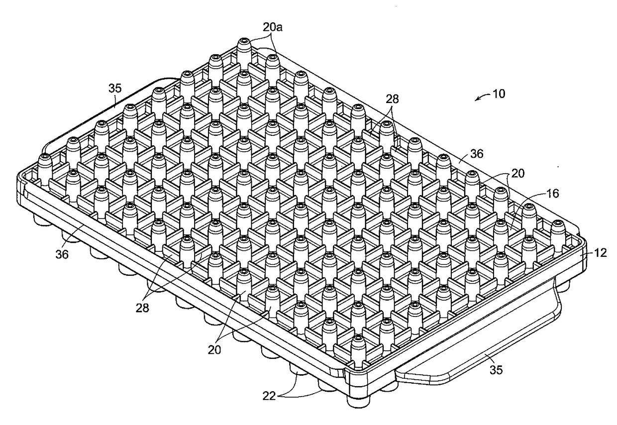
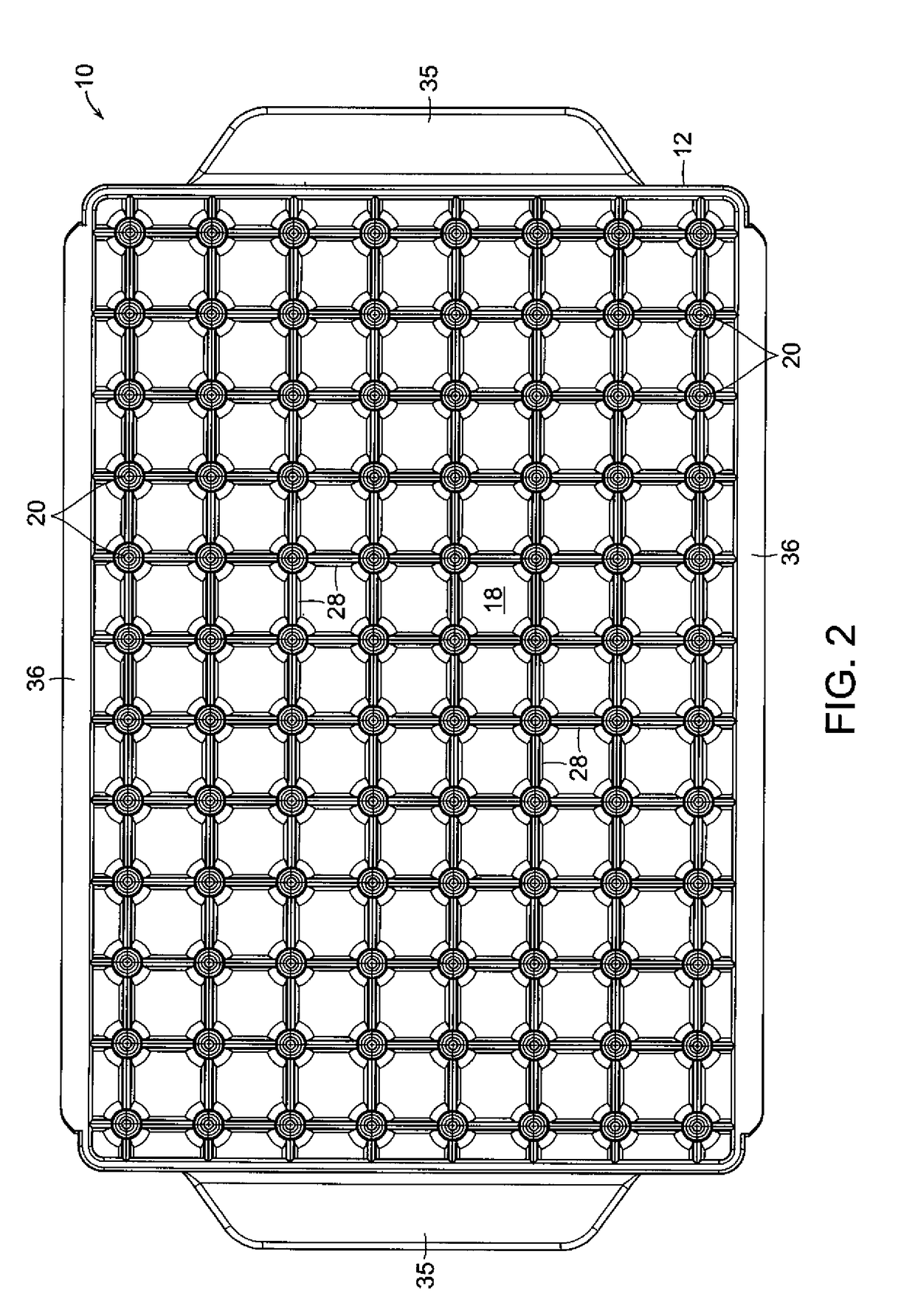
[0024]With reference initially to FIGS. 1- 6, a pipettor tip adapter in accordance with an exemplary embodiment of the present invention is generally indicated at 10. The pipette tip adapter comprises a planar base 12 with an array of openings 14 extending between bottom and top surface 16, 18 of the base.

[0025]Sealing tubes indicated typically at 20 project upwardly from the top surface 16, and tip mounting tubes indicated typically at 22 project downwardly from the bottom surface 18. Pairs of sealing tubes 20 and mounting tubes 22 are arranges coaxially and in communication with respective ones of the openings 14 in the base 12.

[0026]The sealing tubes 20 and tip mounting tubes 22 may be arranged in an array of rows and columns. The spacing of the rows and columns matches the commonly available tip spacing of both multichannel pipettors and associated racks found in the marketplace. These in turn match the well positions of commonly available microtiter plates. Nine and four and a ...


PUM


Abstract

An adapter for connecting an array of pipette tips having through bores with conical upper ends to a multichannel air displacement pipettor having a plurality of ports with compliant internal sealing surfaces. The adapter comprises a planar base with an array of openings extending between its top and bottom surfaces. Sealing tubes project upwardly from the top surface, and tip mounting tubes project downwardly from the bottom surface, with pairs of sealing tubes and tip mounting tubes being arranged coaxially and in communication with respective ones of the openings in the base. The tip mounting tubes are externally dimensioned and configured for insertion into the conical upper ends of the pipette tips, and the sealing tubes are externally configured and dimensioned for insertion into the ports of the pipettor and into sealing interengagement with their compliant internal sealing surfaces.

Description

CROSS REFERENCE TO RELATED APPLICATION[0001]This application claims benefit, under 35 U.S.C. § 119(e), of U.S. Provisional Application Ser. No. 61509577, filed Jul. 20, 2011, the entire contents and substance of which is herein incorporated by reference.BACKGROUND1. Field on the Invention[0002]This invention relates generally to multichannel air displacement pipettors employing disposable pipette tips, and is concerned in the particular with the provision of an adapter for providing an interface between the pipette tips and the pipettor.2. Description of the Related Art[0003]Air displacement pipettors are typically used to transfer liquids between vessels as part of an assay. Common vessels are microtiter plates, test tubes and reservoirs.[0004]Air displacement pipettors frequently make use of a piston and cylinder arrangement, which is used to create positive and negative pressure in an attached pipette tip. When the open end of the tip is placed into a liquid, the change in pressu...

Claims


Application Information

Patent Timeline
Patent Type & Authority Applications(United States)
IPC IPC(8): B01L3/00B01L3/02
CPCB01L3/5025B01L3/0217B01L2200/021B01L2200/023B01L2200/025B01L2200/026B01L2300/0829B01L3/0275B01L3/5635
Inventor COTE, RICHARD
Owner AVIDIEN TECH
Why Eureka
Try Eureka