

High-pass two-dimensional ladder network resonator
a ladder network and resonator technology, applied in the field of radio frequency resonators, can solve the problem of limited application in the higher field of these structures
- Summary
- Abstract
- Description
- Claims
- Application Information
AI Technical Summary
Benefits of technology
Problems solved by technology
Method used
Image

Examples
Embodiment Construction
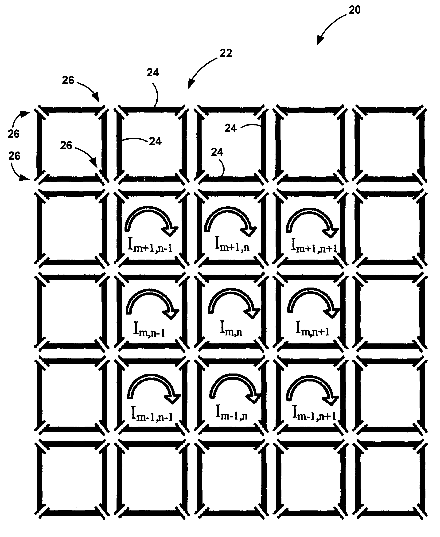
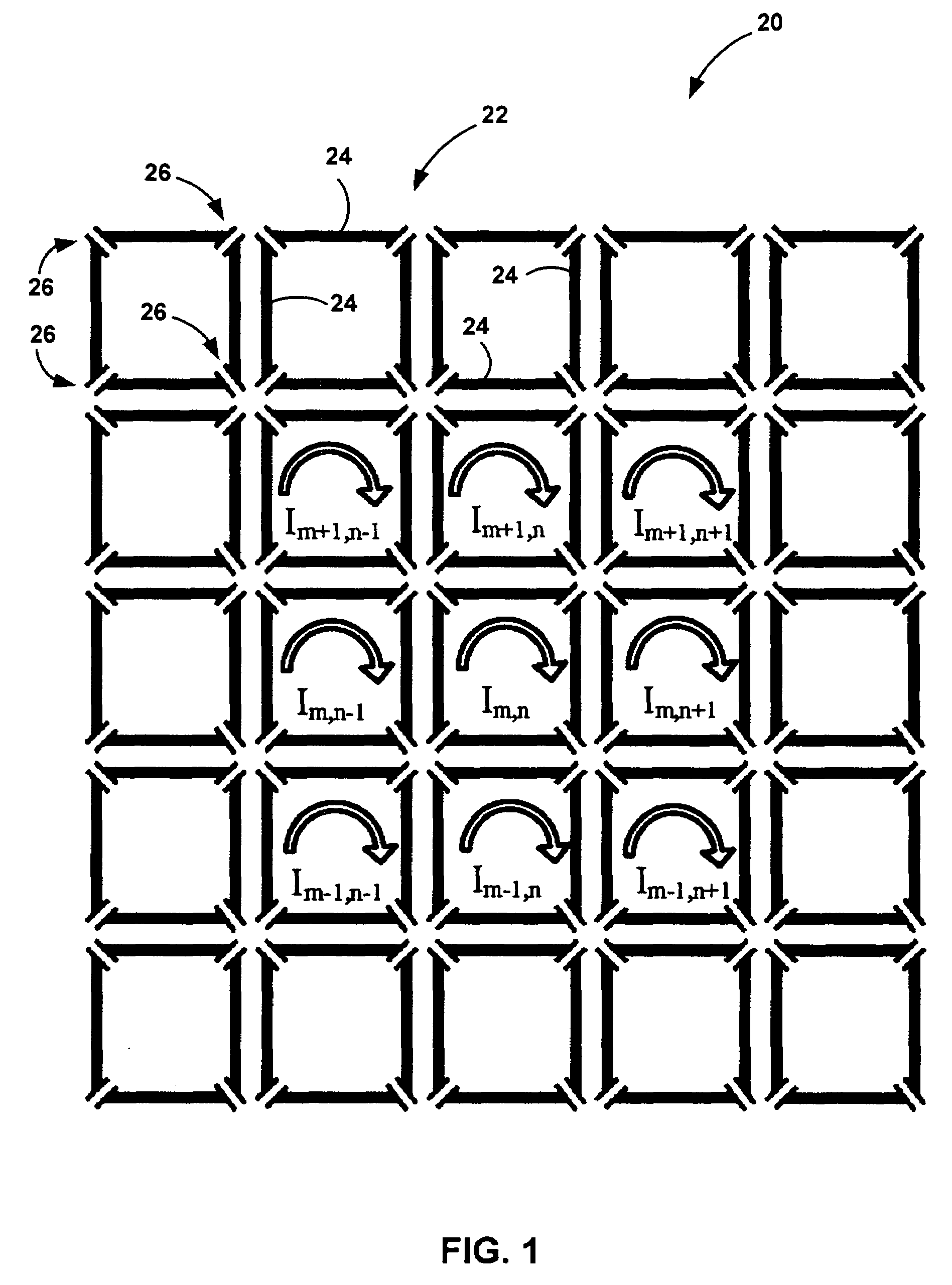
[0044]The invention provides a high-pass two-dimensional ladder network where the next-to-highest eigenvalue corresponds to a normal mode giving rise to B1 fields with good spatial homogeneity above the resonator plane. As such, it can be utilized for linear or quadrature operation with a B1 profile suitable for imaging applications and security applications.
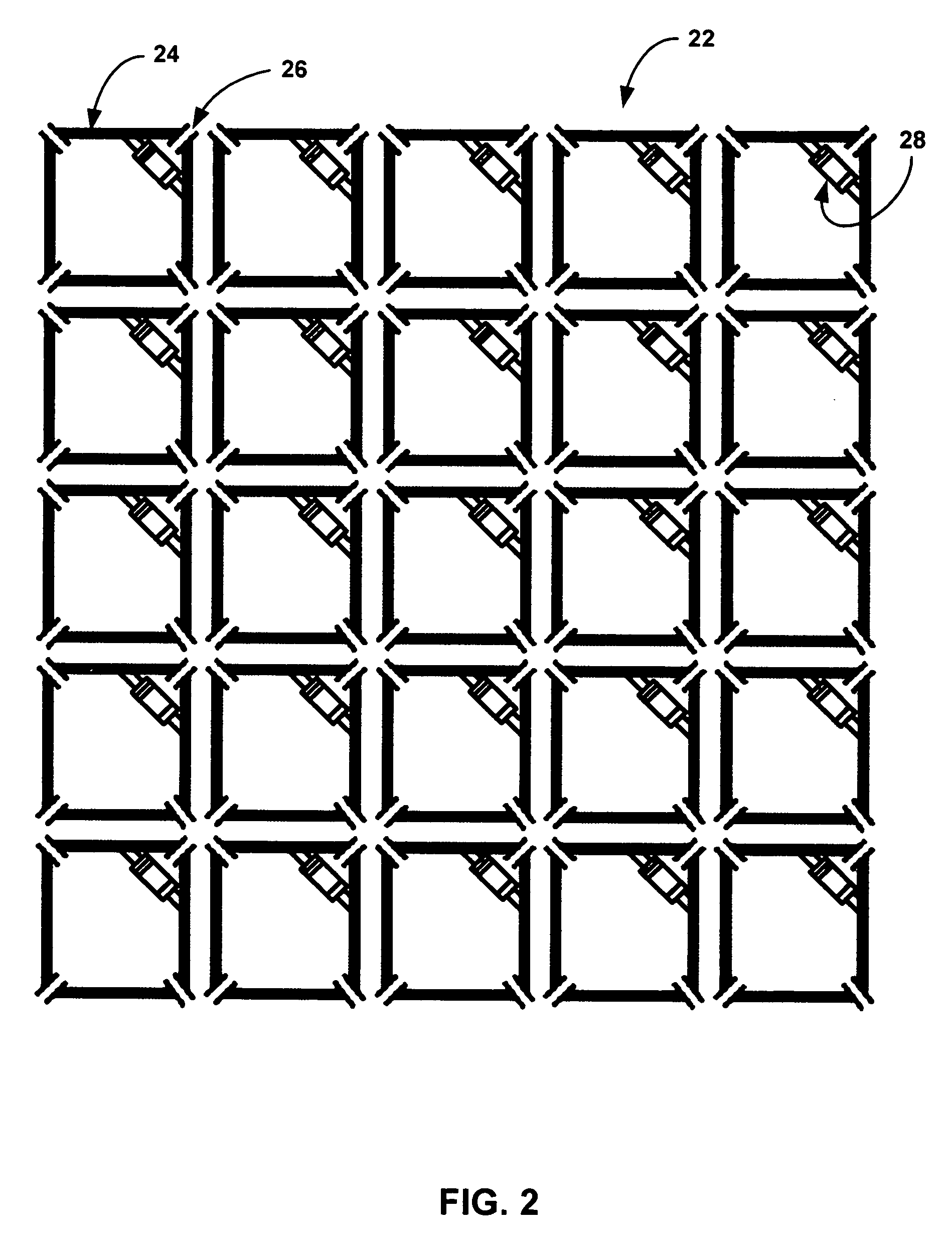
[0045]Turning now to the figures, wherein like reference numerals refer to like elements, an embodiment of the invention is illustrated in FIG. 1. The high-pass two-dimensional ladder network 20 of FIG. 1 is shown as a 5×5 collection of inductively coupled resonators. The resonators are only inductively coupled and do not share any common leg between resonators and may partially overlap other resonators. Each resonator 22 in FIG. 1 is represented by conducting strips 24 having a self inductance L, joined by a capacitor 26 having a capacitance having a value C at each corner. In some applications, the capacitance value may be non...
PUM
 Abstract
Description
Claims
Application Information