Flow Control Apparatus And Medical Injection Circuit Using The Same

Inactive Publication Date: 2009-01-15
JMS CO LTD
View PDF6 Cites 5 Cited by
  • Summary
  • Abstract
  • Description
  • Claims
  • Application Information

AI Technical Summary

Benefits of technology

[0015]Based on the above configuration, according to the flow control apparatus and the injection circuit of present invention, for example, the set pressure of a valve member can be set to be a value higher than that of a flow pressure at a time of the occurrence of free-flow, whereby the occurrence of free-flow can be suppressed. Furthermore, in the flow control apparatus and the injection circuit in the present invention, an

Problems solved by technology

The injection of a transfusion using such transfusion pumps has a free-flow problem.
Furthermore, the free-flow problem may occur even in the case of the administration of a

Method used


Image

  • Flow Control Apparatus And Medical Injection Circuit Using The Same
  • Flow Control Apparatus And Medical Injection Circuit Using The Same
  • Flow Control Apparatus And Medical Injection Circuit Using The Same

Examples


Example

EMBODIMENT 1

[0041]Hereinafter, the flow control apparatus and the injection circuit in Embodiment 1 of the present invention will be described with reference to FIGS. 1 to 10. First, the flow control apparatus in Embodiment 1 will be described using FIGS. 1 to 7.

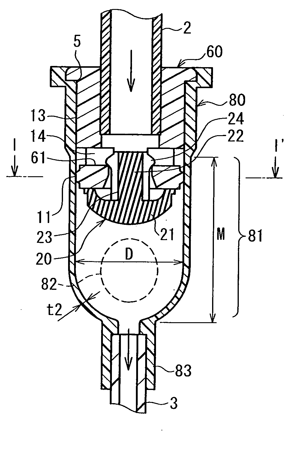
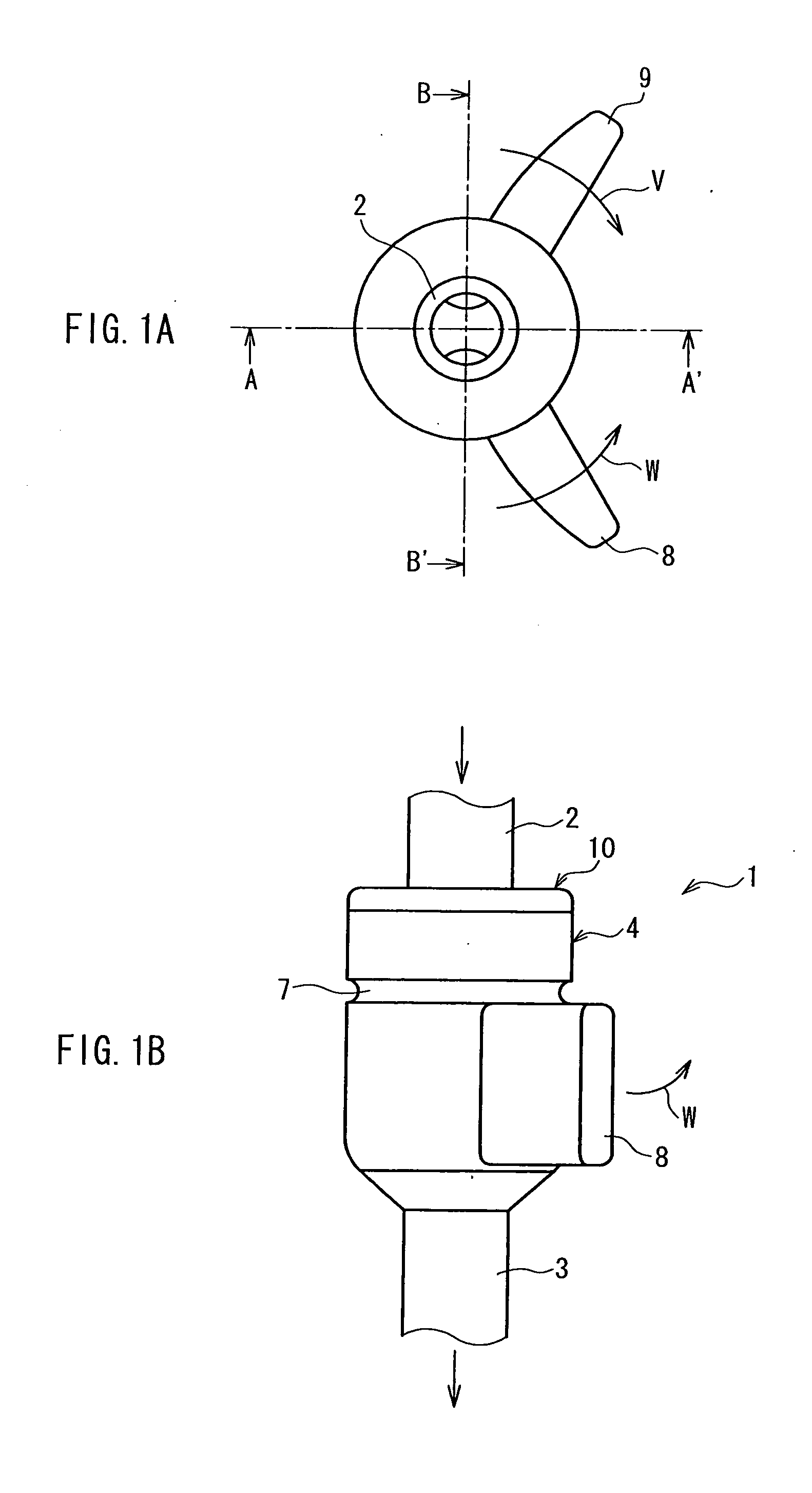
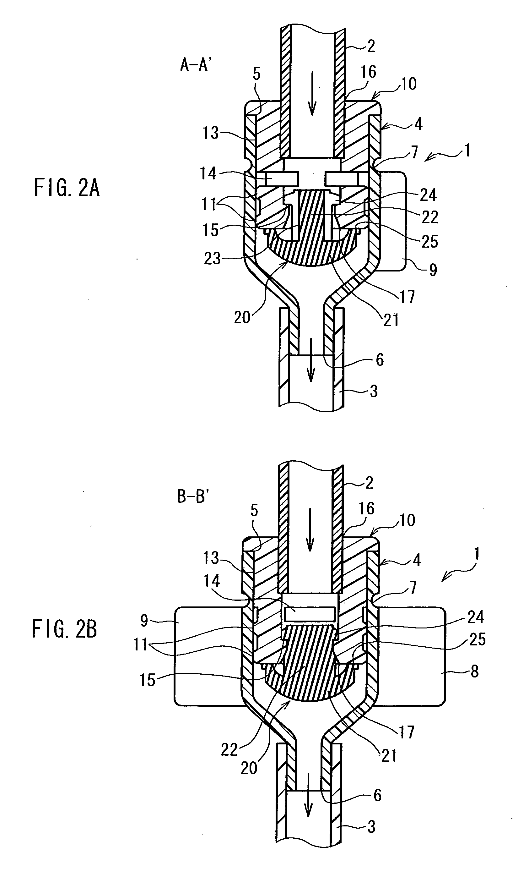
[0042]FIG. 1 shows views illustrating an outer appearance of a flow control apparatus in Embodiment 1 of the present invention, FIG. 1A is a top view, and FIG. 1B is a side view. FIG. 2 shows cross-sectional views illustrating a configuration of the flow control apparatus shown in FIG. 1, FIG. 2A is a cross-sectional view taken along a cut line A-A′ in FIG. 1A, and FIG. 2B is a cross-sectional view taken along a cut line B-B′ in FIG. 1B. In FIGS. 1 and 2, arrows (excluding arrows V and W) represent flow directions of a fluid.

[0043]FIG. 3 is a cross-sectional view showing an outside member constituting the flow control apparatus shown in FIG. 1. FIG. 4 shows views illustrating an inside member constituting the flow control ap...

Example

EMBODIMENT 2

[0091]Next, a flow control apparatus and an injection circuit in Embodiment 2 of the present invention will be described with reference to FIGS. 11 and 12. FIG. 11. FIG. 11 shows cross-sectional views illustrating a cross-sectional configuration of the flow control apparatus in Embodiment 2 of the present invention, and FIGS. 11A and 11B respectively show cross-sections in different cut directions. FIG. 12 shows views illustrating an inside member constituting the flow control apparatus shown in FIG. 11, FIG. 12A is a side view, and FIG. 12B is a cross-sectional view taken along a cut line F-F′ in FIG. 12A.

[0092]The outer appearance of the flow control apparatus in Embodiment 2 is the same as that of the flow control apparatus in Embodiment 1 shown in FIG. 1. FIG. 11A corresponds to a cross-sectional view taken along a cut line A-A′ in FIG. 1, and FIG. 11B corresponds to a cross-sectional view taken along a cut line B-B′ in FIG. 1A. Furthermore, in FIGS. 11 and 12, eleme...

Example

EMBODIMENT 3

[0098]Next, the flow control apparatus and the injection circuit in Embodiment 3 of the present invention will be described with reference to FIGS. 13 and 14. FIG. 13 shows views illustrating an outer appearance of the flow control apparatus in Embodiment 3 of the present invention, and FIGS. 13A and 13B are viewed in different directions. Furthermore, the viewing direction in FIG. 13A is perpendicular to the viewing direction in FIG. 13B. FIG. 14 shows cross-sectional views illustrating a configuration of the flow control apparatus shown in FIG. 13, FIG. 14A is a cross-sectional view taken along a cut line G-G′ in FIG. 13B, and FIG. 14B is a cross-sectional view taken along a cut line H-H′ in FIG. 14A.

[0099]As shown in FIGS. 13 and 14, the flow control apparatus in Embodiment 3 includes the valve member 20, the inside member 60, and an outside member 70, and the outside member 70 is different from those shown in Embodiments 1 and 2. In FIGS. 13 and 14, elements denoted ...


PUM


Abstract

A flow control apparatus 1 including a tubular outside member 4, a tubular inside member 10 placed in the outside member 4, and a valve member 20 is used. The inside member 10 includes a through-hole 14 passing through a side wall in a thickness direction and a contact portion 11 that is in contact with the outside member 4, which are arranged in that order in a direction from one opening 16 to the other opening 17. The valve member 20 is placed in the opening 17 of the inside member 10. The valve member 20 passes only a fluid supplied at a set pressure or higher in a direction from the one opening 16 to the other opening 17. The outside member 4 is formed so as to form a gap communicating with the through hole 14 between the outside member 4 and the contact portion 11 due to elastic deformation caused by an external force. The gap forms a flow path of a fluid in combination with the through-hole 14.

Description

TECHNICAL FIELD[0001]The present invention relates to a flow control apparatus, and in particular, to a flow control apparatus that functions as an anti-free flow mechanism during the injection of a transfusion and the administration of a drug with respect to a patient, and an injection circuit using the flow control apparatus.BACKGROUND ART[0002]Conventionally, in order to define the flow rate of a transfusion to be injected into a patient, a transfusion pump has been used. The transfusion pump is attached to a transfusion circuit connecting a transfusion bag to a puncture needle and provides a transfusion tube constituting the transfusion circuit with a peristalsis, thereby feeding a transfusion at a set flow rate. Furthermore, generally, as the transfusion pump, a finger-type transfusion pump and a roller-type transfusion pump are known.[0003]The finger-type transfusion pump includes a plurality of fingers arranged in a row along a transfusion tube, and allows the plurality of fi...

Claims


Application Information

Patent Timeline
IPC IPC(8): A61M5/31
CPCA61M5/141A61M5/16813F16K15/18A61M2005/1402F16K15/148A61M39/24Y10T137/789
Inventor FUJII, RYOJIYUKI, TAKEHIKO
Owner JMS CO LTD
Why Eureka
Try Eureka