Frictionless hip joint

Active Publication Date: 2020-07-16
NOEL RARES ORTHO DEVICES INC
View PDF0 Cites 0 Cited by
  • Summary
  • Abstract
  • Description
  • Claims
  • Application Information

AI Technical Summary

Benefits of technology

[0028]In general principle, the present invention recognizes that the major axis of motion in a hip joint is that which provides rotation during walking and running movements. While a hip joint provides for other motion, e.g., laterally, these motions are minor in comparison. Accordingly, one aspect of the present invention internalizes at least the major motion interiorly of the orthopedic prosthesis, thereby significantly reducing the wear that otherwise occurs between the head and liner of an ordinary implant, eventually causing such complications as tissue necrosis or pseudo-tumors.
[0029]In at least one embodiment, the present invention is directed to a coaxial, fully articulating joint, which is particularly suitable as an orthopedic hip prosthesis, in which the head includes at least two portions, a proximal member and a distal member. The proximal member is dimensioned and configured to be received directly by the acetabulum, or if not directly, then preferably at least by a thin shell installed within the acetabulum. Such a “thin shell” as may be utilized by certain embodiments of the present invention functionally replaces both the shell and liner of the prior art. The proximal member is disposed in substantially unrestricted relation within the acetabulum in that it is free to rotate within the acetabulum or liner, such that minor motions of the patient's leg, e.g., lateral motions, can be accommodated when desired.
[0030]The distal member is dimensioned and configured to be fixedly connected to a femur of the patient. The distal member may include a shank that is either directly installed within a femur of the patient or may be coupled to a more traditional femur stem, which is in turn installed within the patient's femur. The proximal member and distal member are correspondingly dimensioned and configured to be adjoined at a mating interface, which may be internally of the proximal member, but which constrains movement of the distal member within the proximal member to rotation about a single axis, i.e. a single degree of freedom of movement relative to the proximal member. Preferably, this single degree of freedom of movement is coaxial, when properly implanted within a patient (or installed in a walking mechanism of, e.g., a robot), with the patient's natural axis of rotation of the legs during walking and running motions. Stated otherwise, the distal member may rotate within the proximal member about an axis that can be aligned with the patient's natural axis of rotation of the legs. Accordingly, the major motion of the patient is accommodated interiorly of the orthopedic pr

Problems solved by technology

As is known, a larger head leads to larger volumetric wear, especially consid

Method used


Image

  • Frictionless hip joint
  • Frictionless hip joint
  • Frictionless hip joint

Examples


Example

[0063]Like reference numerals refer to like parts throughout the several views of the drawings.

DETAILED DESCRIPTION OF THE PREFERRED EMBODIMENT

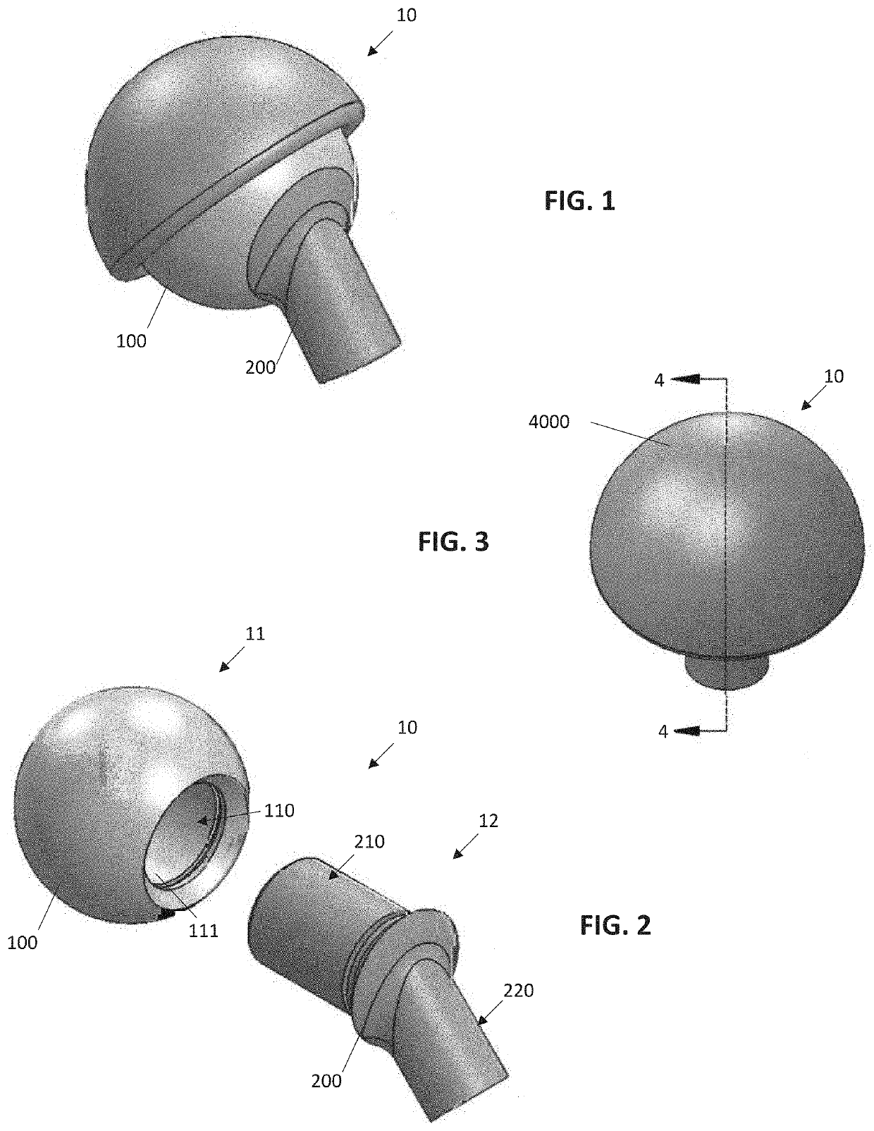
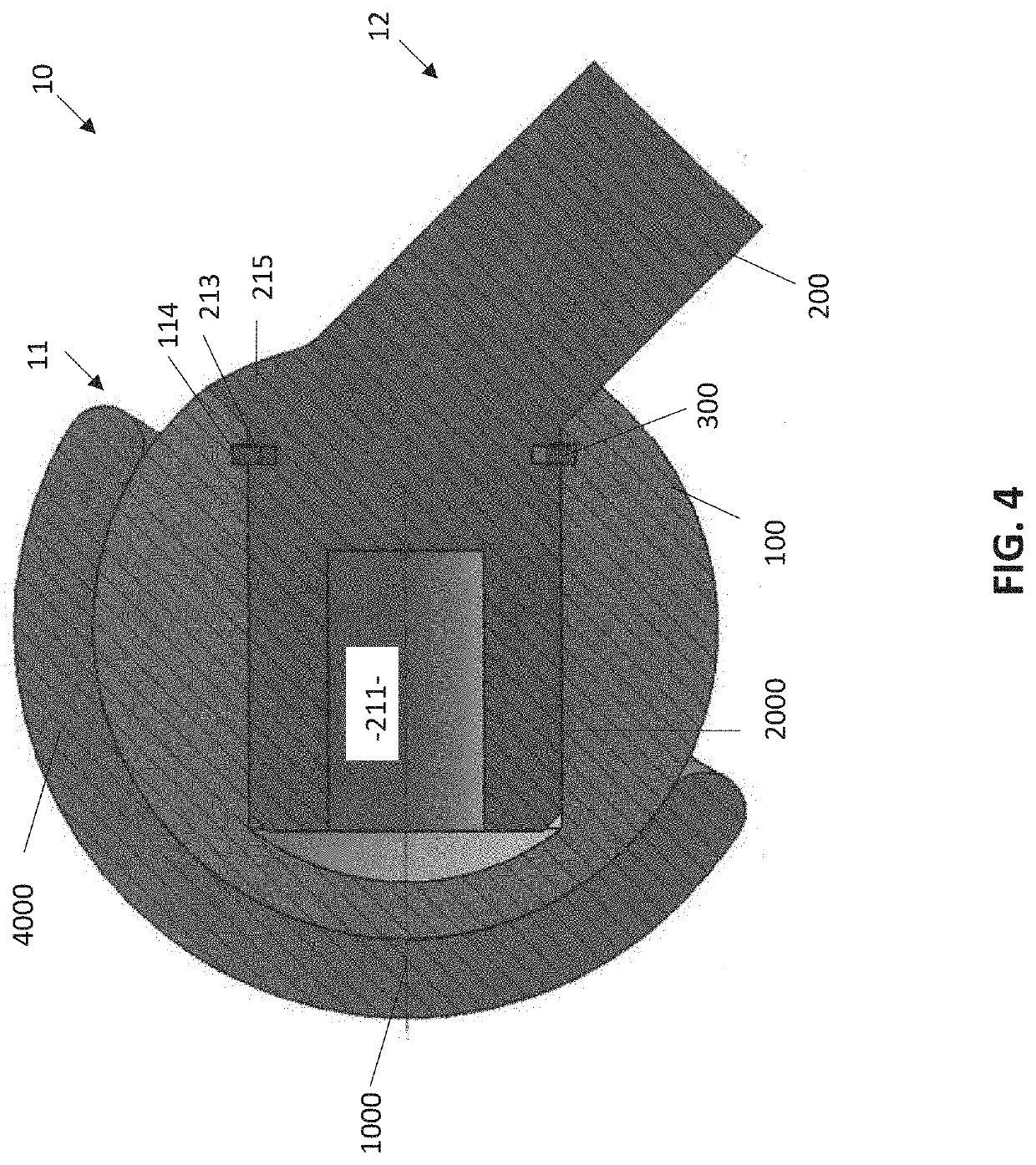
[0064]With reference to FIGS. 1-4, one embodiment of the present invention is directed to an orthopedic hip prosthesis 10 including a proximal member 11 and a distal member 12, as best shown in FIG. 2. The head 100 is a substantially spherical member, which approximates the geometry of a traditional hip replacement prosthesis with notable exceptions. The head 100 will be generally of a larger diameter than its modern equivalents due to the elimination of the “traditional” liner, which tends to be quite thick in dimension, and shell (or, in certain embodiments, replacement of the “traditional” liner and shell with at least a thin shell). Additionally, the head 100 includes a recess 110, such as shown in FIG. 2, with the recess 110 having an inner surface 111.

[0065]Another component of the orthopedic hip prosthesis 10 is the neck 200. The neck ...


PUM


Abstract

An orthopedic prosthesis includes a head which internally accommodates the major motion of a patient, e.g., during walking, thereby reducing wear against a cup or liner. A neck may be utilized which rotates within the distal member about an axis aligned with the major motion of the patient. The orthopedic prosthesis may also include a sacrificial anode, a seal made of natural fibers, and utilize lubricant made of honey.

Description

CLAIM OF PRIORITY[0001]The present non-provisional patent application is a continuation-in-part application of a currently pending and prior filed non-provisional patent application having Ser. No. 15 / 829,267 filed on Dec. 1, 2017, and which claims priority pursuant to 35 U.S.C. Section 119(e) to a provisional patent application having Ser. No. 62 / 491,829 filed on Apr. 28, 2017, the contents of which are incorporated herein by reference in its entirety.BACKGROUND OF THE INVENTIONField of the Invention[0002]The present invention is directed to an improved orthopedic hip prosthesis as well as several advancements in the art including the use of naturally occurring, bio-compatible lubricants, seals made of natural fibers, and the use of a sacrificial anode.Preliminary Statement of the Invention[0003]This device was designed to, among other things, simultaneously:[0004]1) Significantly reduce the current incidents of hip dislocations and the medical care that follows;[0005]2) Eliminate ...

Claims


Application Information

Patent Timeline
IPC IPC(8): A61F2/36A61F2/34A61L27/36
CPCA61F2250/0069A61F2002/3483A61F2/3609A61F2002/365A61F2/34A61F2310/00389A61F2310/00047A61F2002/3615A61L27/36A61L27/3604A61L27/50A61L2400/10A61L2430/24A61F2/32A61F2002/30639A61F2002/3625A61F2002/3652A61F2310/00041A61F2310/00083
Inventor NOEL, HECTOR
Owner NOEL RARES ORTHO DEVICES INC
Why Eureka
Try Eureka