Surfaces and processes for wear reducing in orthopaedic implants

a technology for orthopaedic implants and surfaces, applied in the field of surfaces and processes for reducing friction and wear of orthopaedic implant components, can solve the problems of high wear rate that occurs once the components are installed, increased replacement and revision, and traumatic to surrounding tissue and bone, so as to improve lubricant access and reduce wear ra

Inactive Publication Date: 2003-11-11
SMITH & NEPHEW INC
View PDF23 Cites 160 Cited by
  • Summary
  • Abstract
  • Description
  • Claims
  • Application Information

AI Technical Summary

Benefits of technology

, the reduced-area patterns machined into the mobile bearing tibial insert underside surfaces resulted in reductions in wear rates from 13.4% to 30.5%. This is believed to be primarily a result of the direct reduction of wear area, but other factors such as improved lubricant access (also a result of the machined patterns) and milder tibial platform scratches (an uncontrolled variable) may have also played a role.
The disclosure of devices and processes as recited above is not intended to limit the scope of the present invention. It provides more broadly for artificial joint components to slide without creating advanced stages of wear. Various sizes, geometries, and placements of indentations may be used in order to offer optimal wear reduction. In particular, designs that reduce subsurface stress by decreasing contact area of articulation rather than increasing it can be considered to fall within the scope of this invention.

Problems solved by technology

A common problem involved with joint replacements is the high wear rates that occur once the components have been implanted.
This increased wear causes the need for increased replacements and revisions, which are commonly more labor intensive, more expensive, and more traumatic to the surrounding tissue and bone.
The insert is not constrained, so that it can move in the anterior-posterior direction and / or the medial-lateral direction, which often creates considerable wear.
(Other joints also experience wear due to sliding movement.)
Specifically, the wear mechanisms include adhesive and abrasive wear, generating a large number of relatively small (micrometer and submicrometer) polyethylene wear particles.
The reduction of wear debris generated by orthopaedic devices is one of the leading issues regarding long term performance of orthopaedic joint prostheses.
Wear debris has been associated with adverse biological responses which can lead to local cell death (osteolysis for bone cells), premature loosening and failure of orthopaedic devices, and subsequent need for revision surgery.
Additionally, abrasive third body debris, such as bone cement (for example, polymethylmethacrylate ("PMMA") bone cement) and bone debris may migrate to the interface between bearing or articulating surfaces, further accelerating abrasive wear due to so-called three body motion.
Another factor that can influence implant stability and wear is the frictional force generated at the interface between the bearing surfaces.
For example, many cases of premature loosening of hip components have been attributed to excessive frictional torque between the femoral head and the acetabular component.
Increased friction is also a direct indication of adhesive interaction, or solid--solid contact between bearing surfaces and typically results in increased wear of one, or both bearing surfaces.
As discussed above, one of the problems encountered with mobile bearing systems is the constant wear that occurs between the bearing and the tibial and / or femoral component due to articulation.
These problems are, of course, also encountered with other types of artificial joints.
Additionally, wear particles created by the friction between these materials are suspected as leading to loosening of the prosthesis.
In some instances, however, these lubrication models do not work or cannot be tolerated because they introduce undesired contaminants or other undesired physical characteristics into the process of the device.
Circular diameters greater than 0.8 mm cause the area of the projected portions to decrease so that the projected portions cannot support the loads, sliding and lubricating properties are deteriorated due to wear of the slide surface, and unevenness occurs.
Again, among other things, these references fail to suggest that the depths of the recessed portions can be beyond the 1 mm limitation, as well as fail to consider the anatomical properties and various placements of the portions.
Various concepts that these references do not consider, however, are that if the recessed portions are not sufficiently deep, synovial fluid may fill the recesses and calcify, essentially re-filling the recesses, thus eliminating the benefits sought to be achieved.
Nor do the currently available references consider the benefits of various positionings of the patterns on the surface or the concept of reducing overall areas of wear.
More particularly, about 85% of wear of mobile bearing knee systems occurs on the underside of the mobile bearing device, with only 15% of wear occurring on the topside.
Recent studies conducted on hip replacement systems indicate that the volumetric wear rate of acetabular liners increases with increasing head / cup diameter.
Essentially, increasing the contact surface in this situation increases the wear suffered, rather than decreases the wear.
That is, the increased wear shown suggests that the theory behind "spreading out" contact stress is overshadowed by the fact that increased contact area causes more wear.
This is commonly a source of friction and wear.
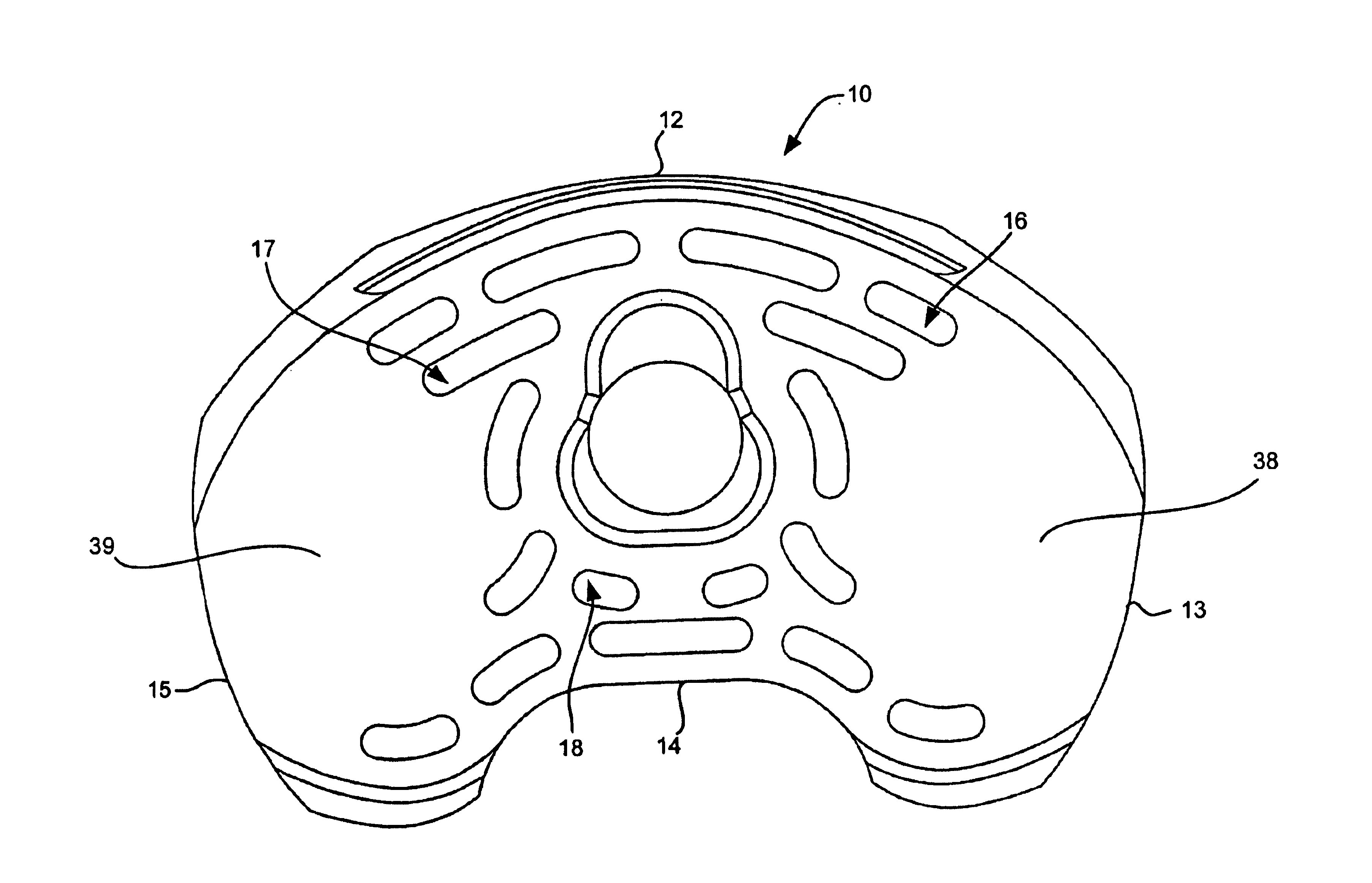
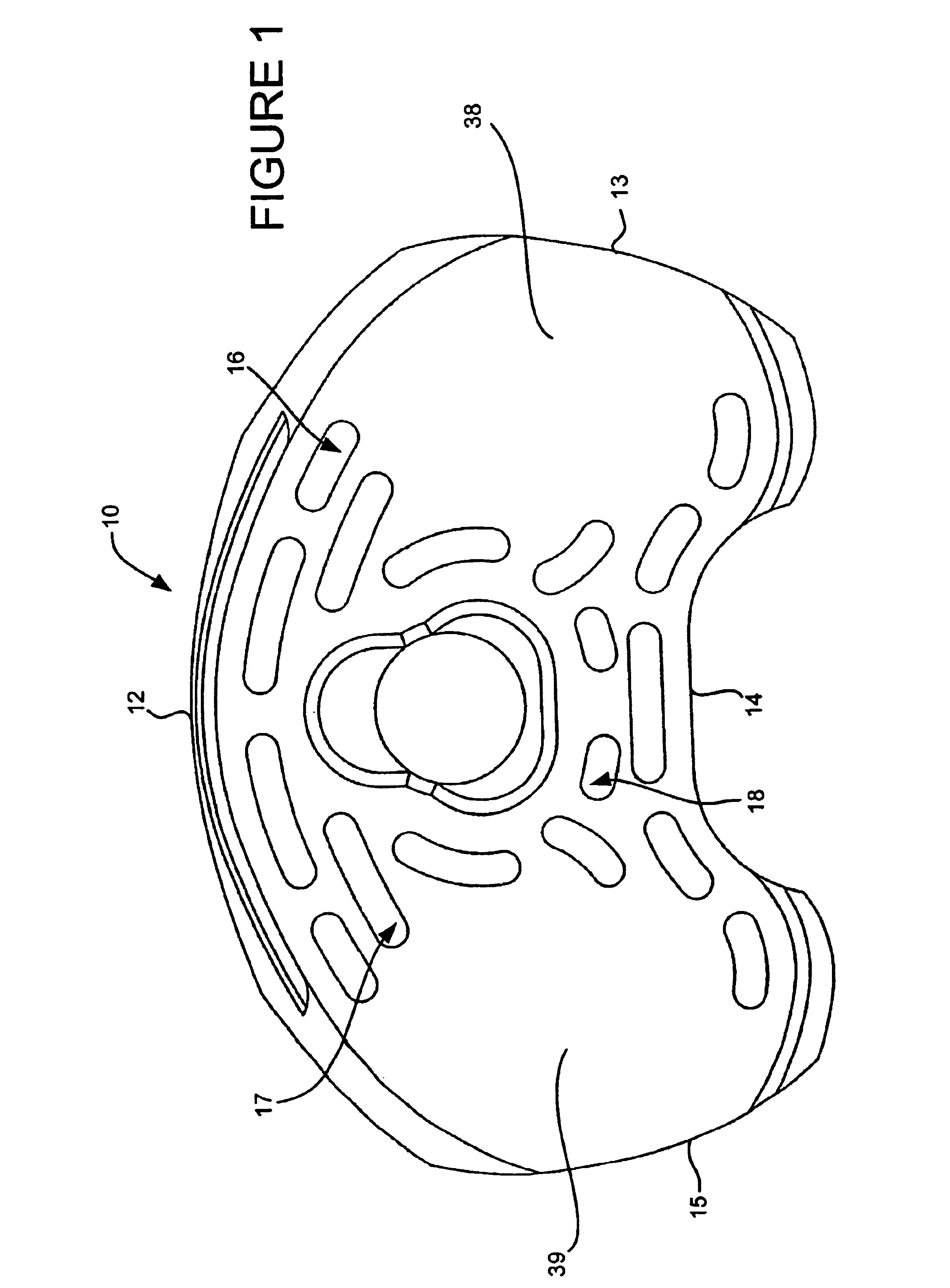
Further, it was shown that a greater percentage of the wear occurred on the underside or inferior portion of the mobile bearing insert.
More specifically, because it has been shown that about 85% of the wear suffered by mobile bearing knee systems occurs on the underside of the mobile bearing device, with only 15% of wear occurring on the topside, the indentations are provided on the underside, or the inferior surface, of the device.
As discussed, these areas tend to show high wear, perhaps even the greatest wear in mobile bearing knee implants.
For design reasons, it may not be desirable to remove area from such locations because of, for example, minimum thickness standards or load bearing considerations.
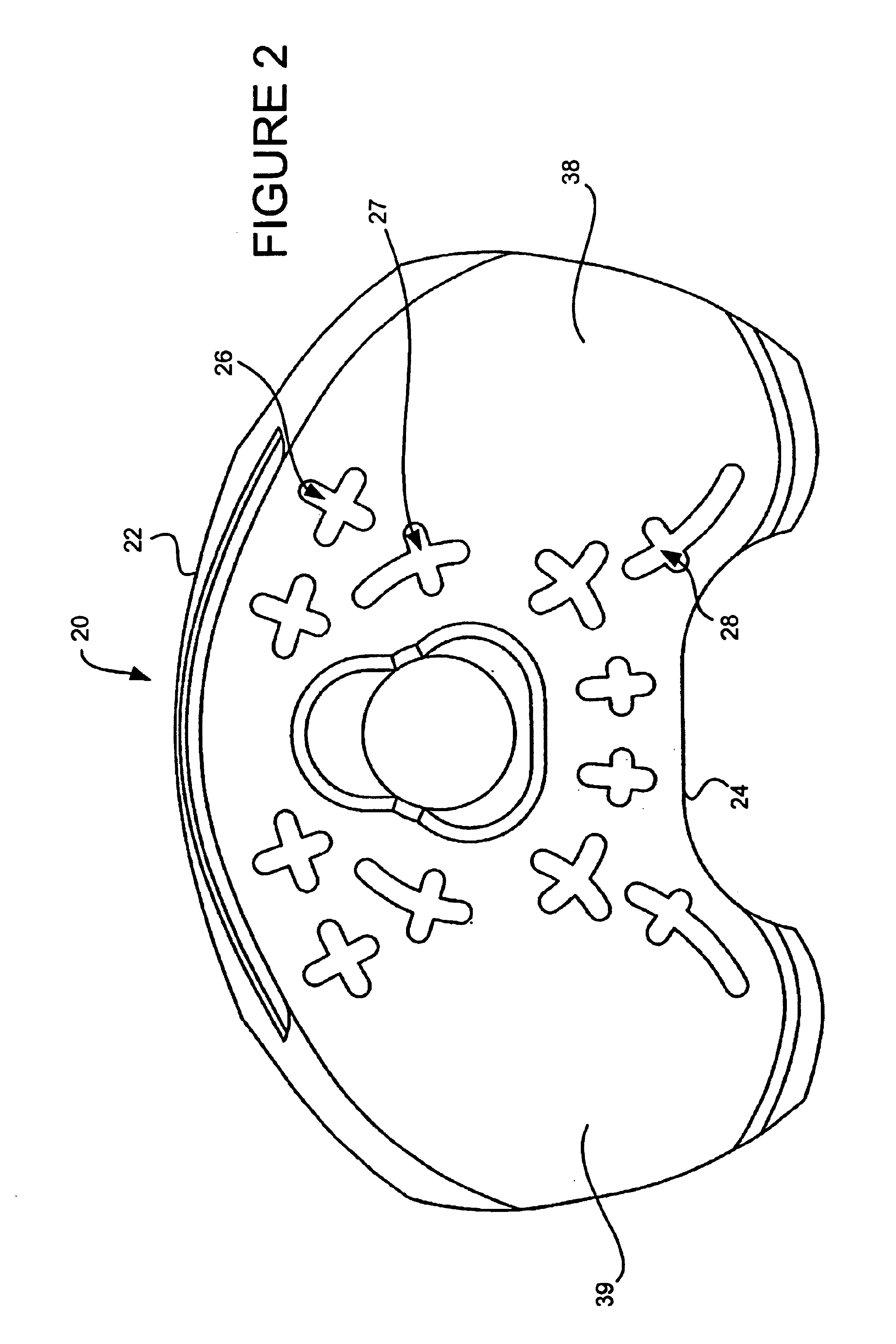
On the other hand, there may be a possibility that wear occurs paradoxically at places where the point loads are not the greatest, so that wear is reduced without negatively creating excess deformation of the component by reducing surface area at places where point loads are.
There is still a great amount of wear produced on other areas of the insert.

Method used


Image

  • Surfaces and processes for wear reducing in orthopaedic implants
  • Surfaces and processes for wear reducing in orthopaedic implants
  • Surfaces and processes for wear reducing in orthopaedic implants

Examples


Embodiment Construction

Standard mobile bearing inserts (MBK-1) with various underside reduced-area patterns were prepared. The selection of patterns was based on the following criteria:

machining feasibility;

maximum removal of material with minimum effect on integrity;

maintain a minimum distance between holes or slots;

remove no more than 2 mm depth of material; and

avoid holes or slots within 2 mm of edge or directly under center of tibial plateaus (to maintain 6 mm thickness).

Although the patterns were selected using the above criteria, the listed criteria is not critical, and any other possible patterns that could have been chosen are within the spirit and scope of this invention. As discussed, the primary goal is to reduce surface area.

Patterns with crosses (X), slots (S), and holes (C), and were conceived and are shown in FIGS. 1-4. The proportions shown are relatively accurate to those used, although they may be varied in actual practice as necessary. The reduction in underside area for each of these s...


PUM


Abstract

Artificial implants having reduced area to provide reduced wear are provided. The reduced area is particularly located at areas where greatest wear is exhibited. In a particular embodiment of a mobile bearing knee implant, the area is reduced on the mobile bearing insert underside, where it contacts a tibial component. The reduced area may be any shape of indentations, for example, grooves, dimples, straight patterns, curved patterns, crossing patterns, holes, channels or slots. The indentations may be various sizes, and have been found to be particularly effective if covering about 10% to about 20% of the insert at depths between about 1-2 mm.

Description

1. Field of the InventionThe present invention relates to devices, structures and processes for reducing friction and wear of orthopaedic implant components, particularly bearing components, and more particularly ultra-high molecular weight polyethylene (UHMWPE) components, by providing certain novel textured or patterned surfaces on such components.2. Description of Related ArtOrthopaedic implants are becoming increasingly prevalent as millions of patients have been relieved of suffering from joint degenerative diseases and other conditions that affect proper hip, knee, shoulder and other joint function. Total or partial joint replacement procedures involve removal of damaged parts of the relevant joint and replacing them with prosthetic components. During surgery, implant components especially selected to match the patient's needs are located and implanted in the bones forming the joint. In a total joint replacement, it is often the case that a bearing component is interposed betw...

Claims


Application Information

Patent Timeline
Patent Type & Authority Patents(United States)
IPC IPC(8): A61F2/30A61F2/38A61F2/00A61F2/46
CPCA61F2/30771A61F2/3868A61F2310/00029A61F2/3859A61F2/389A61F2/468A61F2002/30133A61F2002/30163A61F2002/30179A61F2002/30673A61F2002/30685A61F2002/30808A61F2002/30825A61F2002/30827A61F2002/30937A61F2230/0015A61F2230/0028A61F2230/0058A61F2/38
Inventor SALEHI, ABRAHAMHARBAUGH, MARKSAUER, WILLARD L.CARSON, CHRISTOPHER PATRICK
Owner SMITH & NEPHEW INC
Why Eureka
Try Eureka