Distributing valve for concrete pump, concrete pump, control method thereof and concrete pump truck

A technology of concrete pump and distribution valve, applied in pump control, pump, piston pump and other directions, can solve the problems of fast wear rate of S-shaped elbow 121, shortening the service life of S-shaped elbow 121, affecting the suction performance of concrete pump, etc. , to achieve high pressure bearing capacity and improve the effect of suction performance

Inactive Publication Date: 2010-07-28
三一西北重工有限公司
View PDF0 Cites 34 Cited by
  • Summary
  • Abstract
  • Description
  • Claims
  • Application Information

AI Technical Summary

Problems solved by technology

The disadvantage of the S-type distribution valve 120 is that the S-shaped elbow 121 of the S-type distribution valve 120 is located in the hopper 110, occupies a part of the volume of the hopper 110, and will adversely affect the flow of concrete slurry, thereby affecting the concrete pump. In addition, the pumping and suction of the conveying cylinder need to be carried out through the S-shaped elbow 121, which also makes the S-shaped elbow 121 wear quickly, thereby shortening the service life of the S-shaped elbow 121

Method used


Image

  • Distributing valve for concrete pump, concrete pump, control method thereof and concrete pump truck
  • Distributing valve for concrete pump, concrete pump, control method thereof and concrete pump truck
  • Distributing valve for concrete pump, concrete pump, control method thereof and concrete pump truck

Examples


Embodiment 1

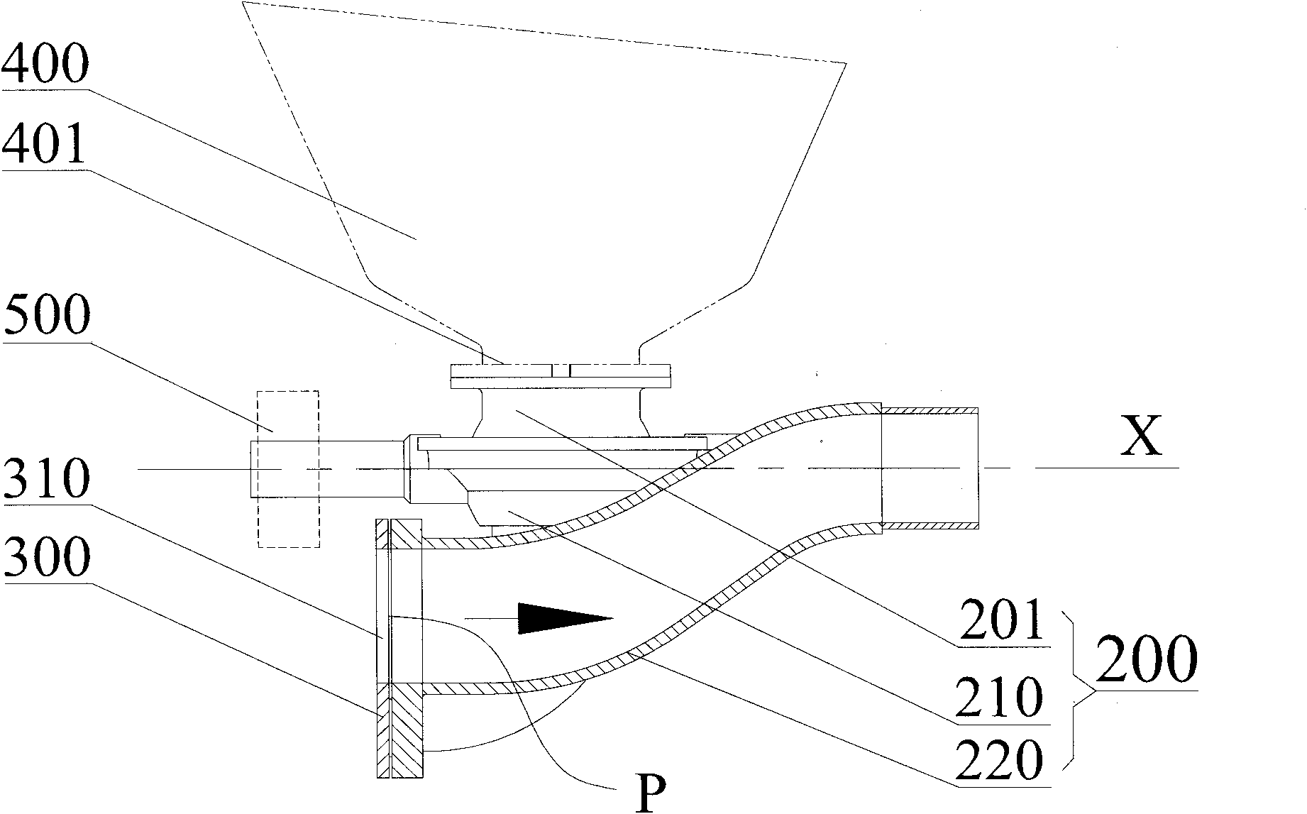
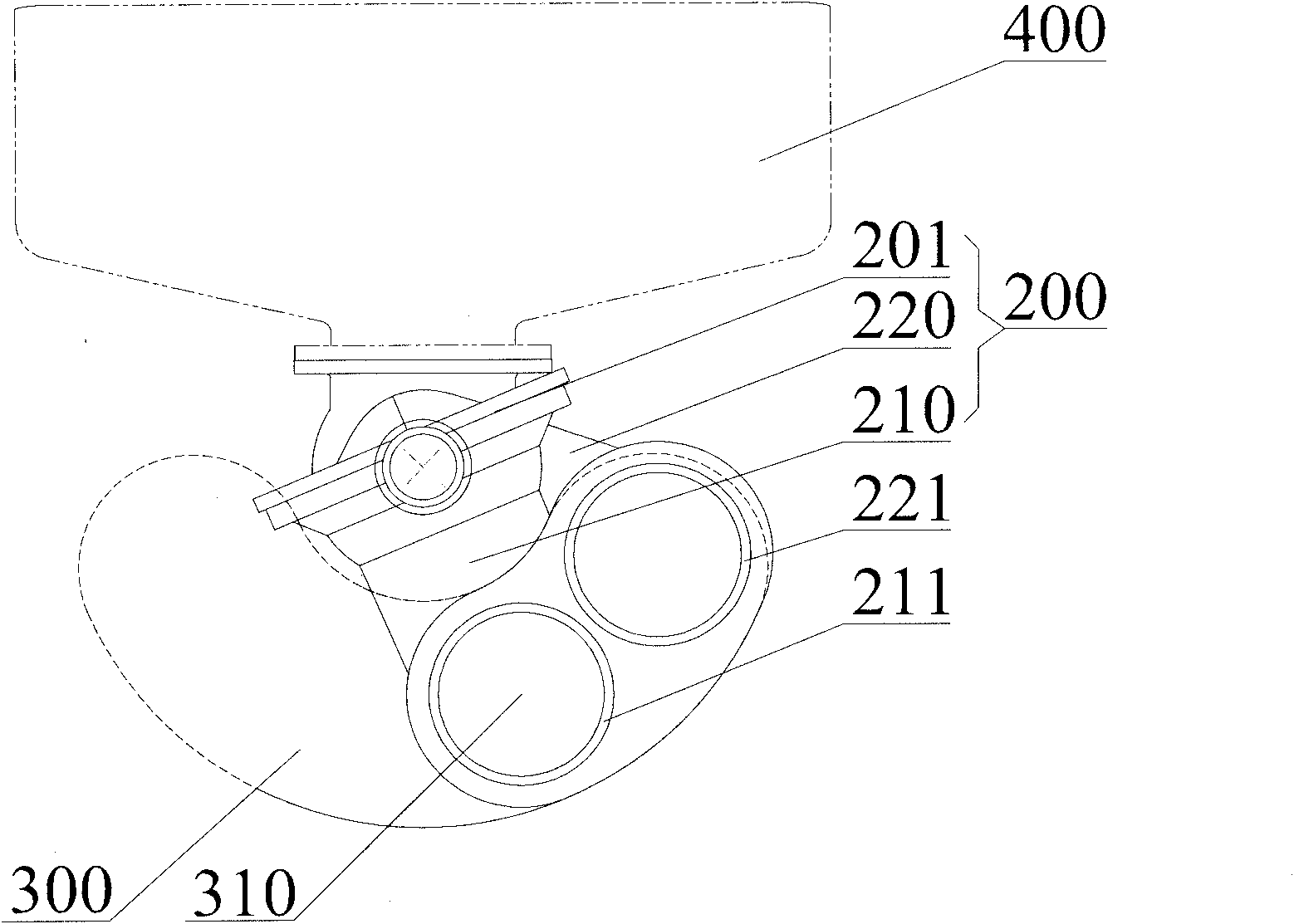
[0059] The distribution valve for a concrete pump provided in Embodiment 1 includes a valve body 200 and a wear plate 300 . The valve body 200 includes a first material suction pipe 210 and a first pump material pipe 220, the front ends of the first material suction pipe 210 and the first pump material pipe 220 respectively have a cutting ring 211 and a cutting ring 221, the cutting ring 211 and the cutting ring The ring 221 is used in conjunction with the wear-resistant plate 300; the wear-resistant plate 300 can have the same material and performance as the spectacle plate in the prior art. When the distributing valve is in state transition, the cutting ring 213 and the cutting ring 214 slide along the working surface P of the wear-resistant plate 220 on the predetermined road section respectively, so that the holes of the cutting ring 213 and the cutting ring 214 respectively contact with the wear-resistant plate at a certain period. The feeding hole 310 on the 300 communic...

Embodiment 2

[0077] The three pipes of the distributing valve body 200 provided in the second embodiment are relatively fixed, and can be driven by the driving mechanism 500 to perform rotary swinging as a whole, and switch from one state to another. This structure has the advantages of simple structure and convenient control. specialty.


PUM


Abstract

The invention discloses a distributing valve for a concrete pump, the concrete pump, a control method thereof and a concrete pump truck. The distributing valve for the concrete pump comprises a valve body and a wear-resisting plate. The valve body comprises a first suction pipe and a first pumping pipe, wherein the back end of the first suction pipe is communicated with an outlet of a hopper so as to communicate the hopper and a delivery cylinder, and the back end of the first pumping pipe is rotatably connected with a delivery pipe of the concrete pump so as to communicate the delivery cylinder and the delivery pipe. The valve body can be switched between a first state and a second state under the driving of a drive mechanism, in the first state, concrete slurry is sucked into the delivery cylinder through the first suction pipe, and in the second state, the delivery cylinder pumps over the concrete slurry through the first pumping pipe. Because of the distributing valve with the structure, the concrete pump can thoroughly employ the self-flowing capacity of the concrete slurry in order to increase the suction performance of the concrete pump. The distributing valve has higher pressure bearing capacity, and the concrete pump can ensure that the concrete slurry has higher pressure through the delivery cylinder, thereby meeting the needs of high-pressure pumps to pump over the concrete slurry.

Description

technical field [0001] The invention relates to a concrete pump technology, in particular to a distribution valve for a concrete pump, and also to a concrete pump with the distribution valve, a control method and a concrete pump truck. Background technique [0002] Concrete pumps are one of the most widely used concrete machines at present. Concrete pumps generally include hoppers, delivery cylinders, distribution valves and delivery pipes. The hopper is used to store concrete slurry, the delivery cylinder is driven by the hydraulic cylinder to perform telescopic movement, and the distribution valve is used to connect the delivery cylinder with the hopper within a predetermined first time, so that the delivery cylinder can absorb material and an appropriate amount of concrete slurry; In the second time, the conveying cylinder is communicated with the conveying pipe, so that the conveying cylinder pumps the material, and the inhaled concrete slurry is pressed into the conveyi...

Claims


Application Information

Patent Timeline
Patent Type & Authority Applications(China)
IPC IPC(8): F04B53/10F04B15/02F04B49/22
CPCF04B15/02F04B15/023B65G53/56B65G53/32F04B7/0096Y10T137/86493F04B49/22F04B53/10
Inventor 易秀明张春光柳桂锋
Owner 三一西北重工有限公司
Why Eureka
Try Eureka