Patellar implant and knee prosthesis incorporating such an implant

a technology of patellar implant and knee prosthesis, which is applied in the field of patellar implant and to total or partial knee prosthesis incorporating such an implant, can solve the problems of increasing the wear of the articular surface in contact, unnatural positioning of the patella, and reducing the efficiency of the extensor muscl

Inactive Publication Date: 2004-10-12
CORIN
View PDF8 Cites 167 Cited by
  • Summary
  • Abstract
  • Description
  • Claims
  • Application Information

AI Technical Summary

Benefits of technology

Thanks to the invention, the congruence of the articular surfaces provided on the implant and the trochlea is widely improved with respect to the state of the art. In particular, the concavity of the outer articular surface in the two planes perpendicular with respect to each other makes it possible to increase the stability of the contact and to reduce the wear of this surface. This double concavity, possibly associated with the convexity of the inner articular surface, also makes it possible to adjust the patella by a pivoting about the outer side of the femur, with the result that the implant and the patella are permanently correctly positioned with respect to the condyles and to the trochlea, without loss of congruence. The curved nature of the ridge contributes to the definition of the outer articular surface and is compatible with the afore-mentioned movement of adjustment, this ridge being engaged in the trochlea. It is a deliberate object of the invention to promote the congruence of the outer articular surfaces respectively provided on the implant and at the level of the outer side of the trochlea or of the outer condyle, whether it be question of a natural condyle or of a prosthetic element, as the bearing efforts of the patella on the condyles essentially transit via these outer surfaces.
Two lateral bevels extend in directions substantially perpendicular to the sagittal plane and join the respective ridges of the articular surfaces to a peripheral edge of the implant. These bevels avoid a possible blocking of the implant on a corner or an edge of a femoral prosthetic surface.
The implant is composed of a one-piece plastics component which allows it to have a sufficient thickness, without risk of metal / metal contact between the femoral prosthetic element and a reinforcing plate such as exists in an implant made of two materials.

Problems solved by technology

This imperfect congruence between the articular surfaces provided respectively on the patellar implant and on the femur also results in a medio-lateral instability of the patella, which may lead to an unnatural positioning of the patella.
This lack of congruence also induces an instability of the patella when pivoting in the sagittal plane, this reducing the efficiency of the extensor muscle and tending to increase wear of the articular surfaces in contact.
Taking these limitations into account, such an implant must be fitted very precisely, otherwise it cannot perform its function.

Method used


Image

  • Patellar implant and knee prosthesis incorporating such an implant
  • Patellar implant and knee prosthesis incorporating such an implant
  • Patellar implant and knee prosthesis incorporating such an implant

Examples


Embodiment Construction

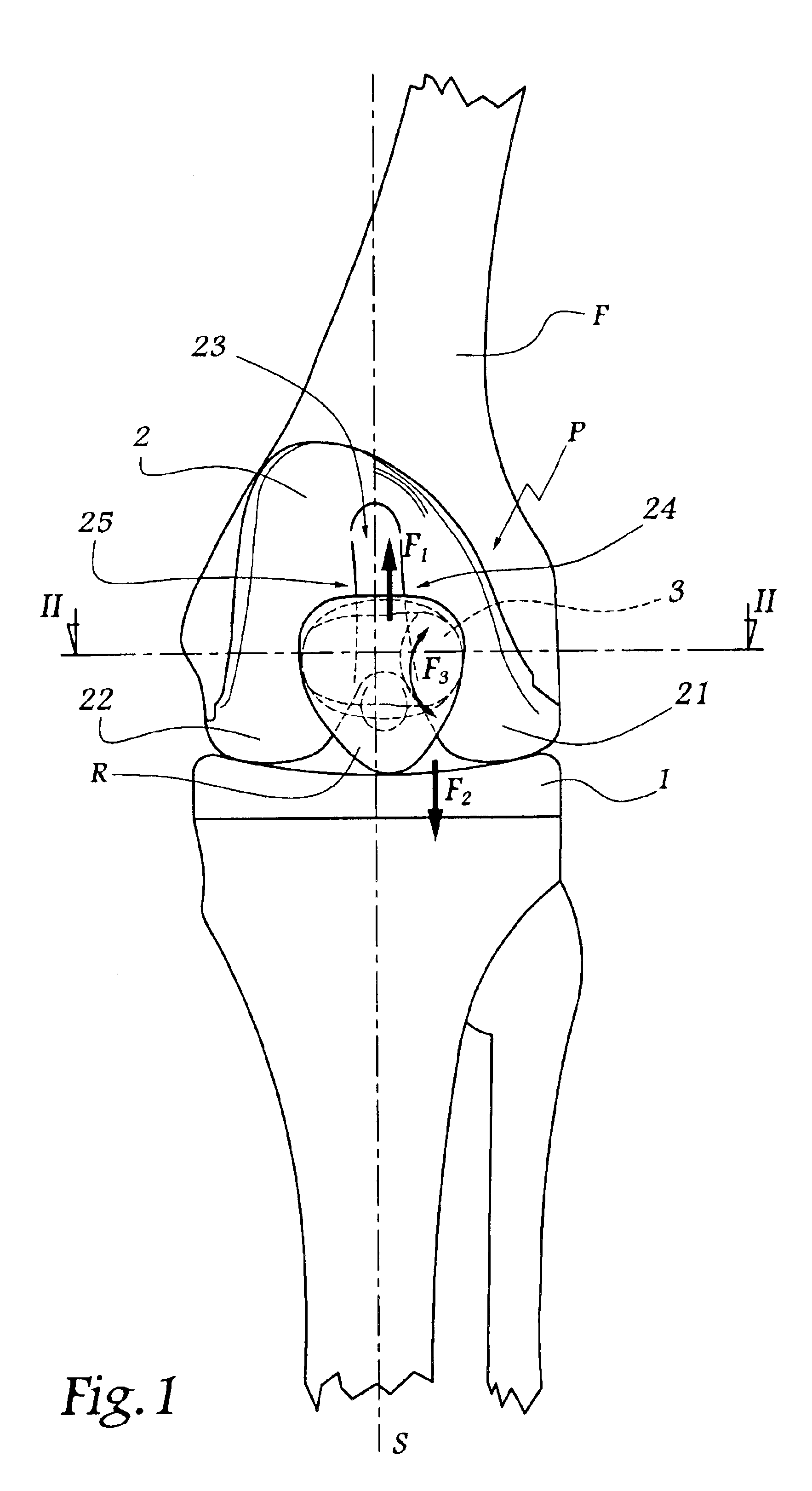
Referring now to the drawings, the prosthesis P shown in FIG. 1 comprises a tibial prosthetic component 1, a femoral prosthetic component 2 and a patellar implant 3 intended to be implanted in the patella R after resection thereof.

In the example shown, the knee in question is a left knee, thus its inner side is located on the left in FIG. 1 while its outer side is on the right.

The component 2 forms two condyles 21 and 22, respectively outer and inner, as well as two outer (24) and inner (25) sides of the femoral trochlea. These two condyles and these two sides are intended to receive the implant 3 in abutment.

The implant 3 is capable of movements of translation with respect to the trochlea 23 defined by the component 2, such movements being represented by arrows F.sub.1 and F.sub.2.

The implant 3 is also capable of movements of pivoting about the condyle 21, as represented by double arrow F.sub.3.

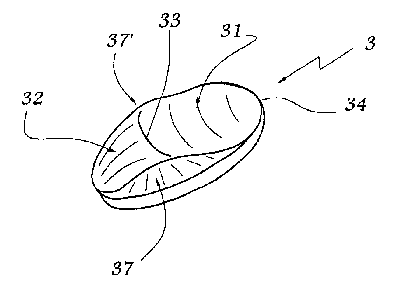
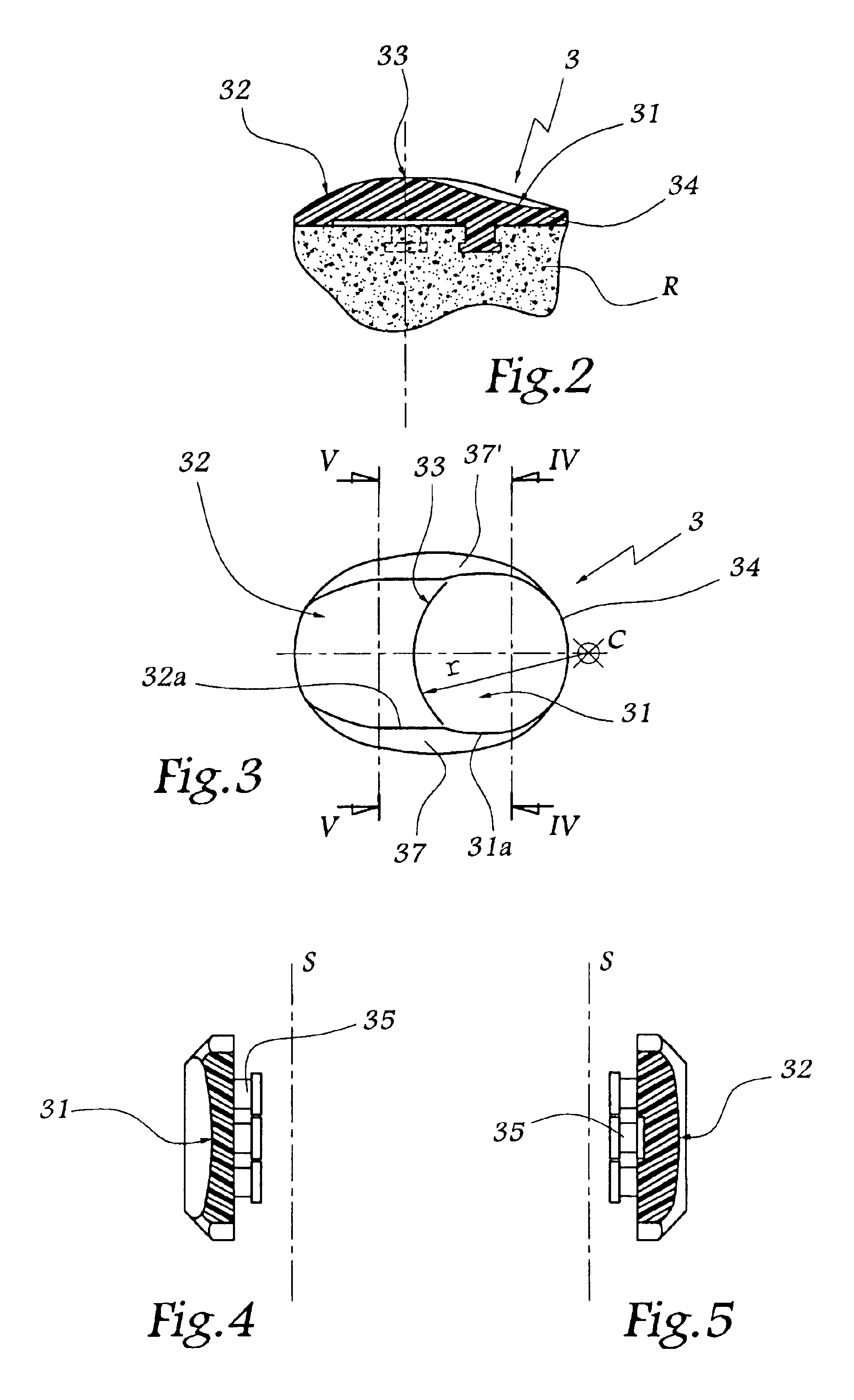
The geometry of the implant 3 may be seen in FIGS. 2 to 7.

This implant comprises an oute...


PUM

PropertyMeasurementUnit
center of curvatureaaaaaaaaaa
shapeaaaaaaaaaa
stabilityaaaaaaaaaa

Abstract

A patellar implant for total or partial prosthesis of the knee joint incorporates an outer articular surface and an inner articular surface provided to cooperate respectively with an outer side and an inner side of a femoral trochlea or of a femoral prosthetic component. The inner and outer articular surfaces are separated by a transition ridge which is curved, as viewed from a front of the implant, so as to be concave facing the outer articular surface. The outer articular surface is concave in a plane parallel to a sagittal plane and in a transverse plane of the knee joint.

Description

Field of the InventionThe present invention relates to a patellar implant and to a total or partial knee prosthesis incorporating such an implant.DESCRIPTION OF THE RELATED ARTIn the domain of knee prostheses, it is known to fit a natural patella with an implant intended to form one or more articular surfaces provided to cooperate with the femoral articular surfaces, whether it be question of natural surfaces or, most often, of prosthetic surfaces.It is known, for example from U.S. Pat. No. 5,609,640 or from EP-A-0 021 421, to produce a patellar implant in the shape of a spherical dome or mushroom. Taking into account its geometry, such an implant is in point or virtually point contact with each condyle, which induces considerable localized stresses in the implant, on the one hand, and in the femoral prosthetic component or the femur, on the other hand. It is also known from FR-A-2 700 260 to produce a patellar component with two articular surfaces, of spherical and concave shape, w...

Claims


Application Information

Patent Timeline
Patent Type & Authority Patents(United States)
IPC IPC(8): A61F2/38A61F2/30A61F2/00A61F2/46A61L27/00
CPCA61F2/3877A61F2002/30125A61F2002/30181A61F2002/30233A61F2230/0069A61F2002/30892A61F2002/4631A61F2230/0008A61F2230/006A61F2002/30805
Inventor TORNIER, ALAIN
Owner CORIN
Why Eureka
Try Eureka