Push-on switch

a push-on switch and switch technology, applied in the direction of rivet contacts, tactile feedback, electric devices, etc., can solve the problems of difficult to further downsize the housing b>1/b> or reduce the thickness of the housing b>1/b>, light weight and yet sophisticated,

Inactive Publication Date: 2012-09-27
PANASONIC CORP
View PDF5 Cites 7 Cited by
  • Summary
  • Abstract
  • Description
  • Claims
  • Application Information

AI Technical Summary

Benefits of technology

[0012]A housing, outer fixed contacts, center fixed contact of the conventional push-on switch are changed into a laminated structure, i.e. two sheets of contact plates made of conductive thin metal sheet are bonded to a spacer

Problems solved by technology

In recent years, a variety of electronic devices has been downsized, light-weighted, and yet sophisticated.
This structure tends to invite a shortage of synthetic resin

Method used


Image

  • Push-on switch
  • Push-on switch
  • Push-on switch

Examples


Embodiment Construction

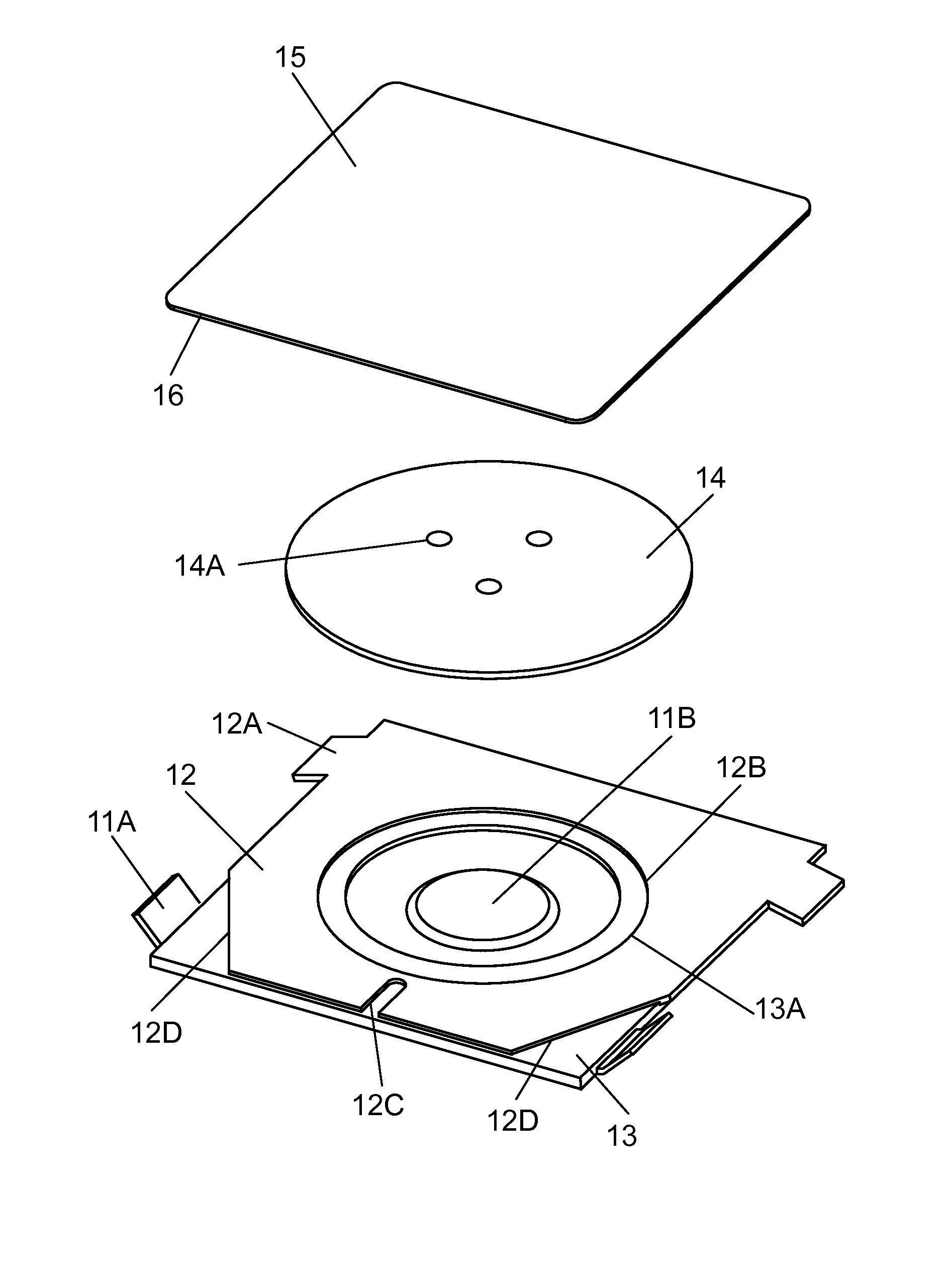
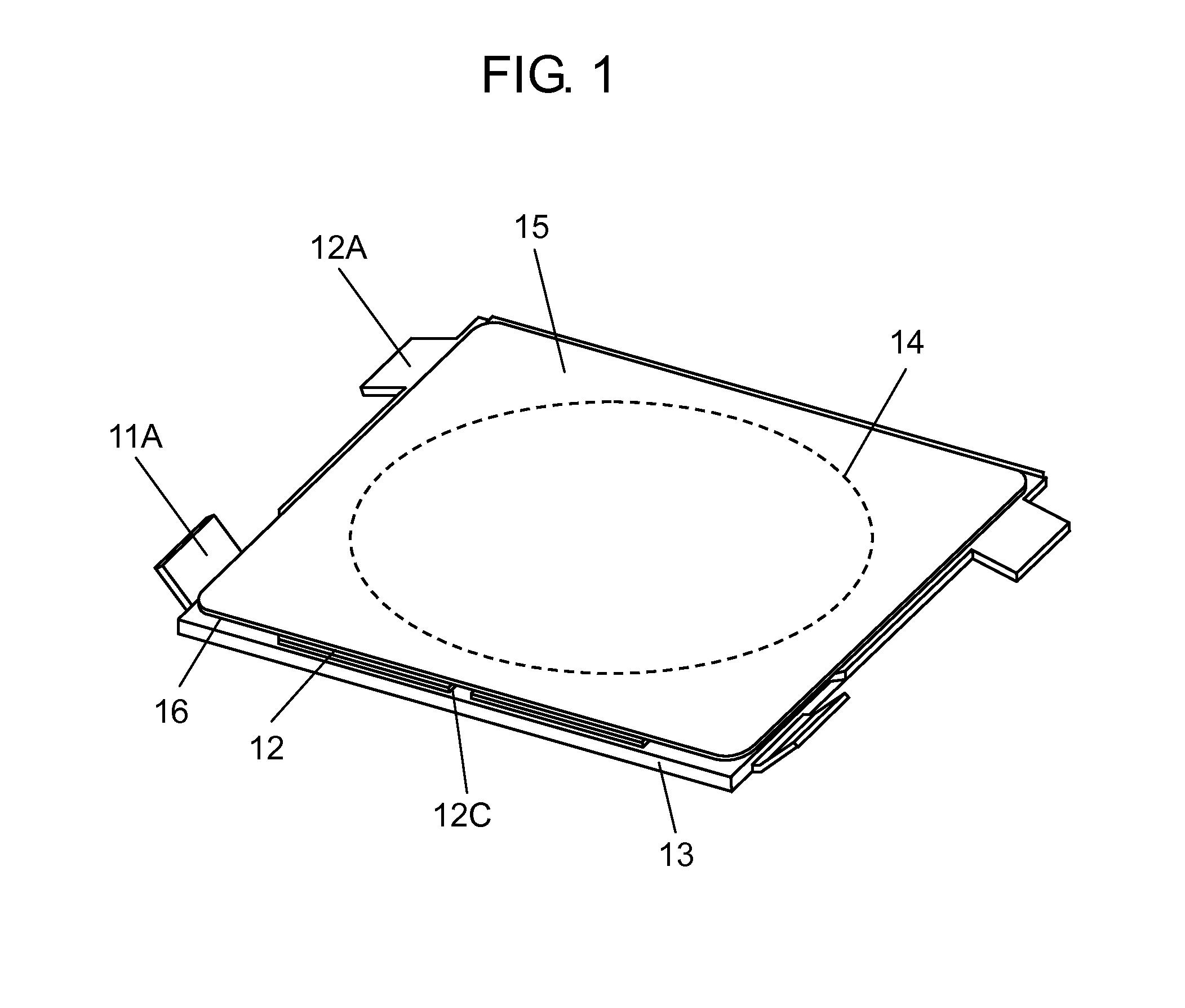
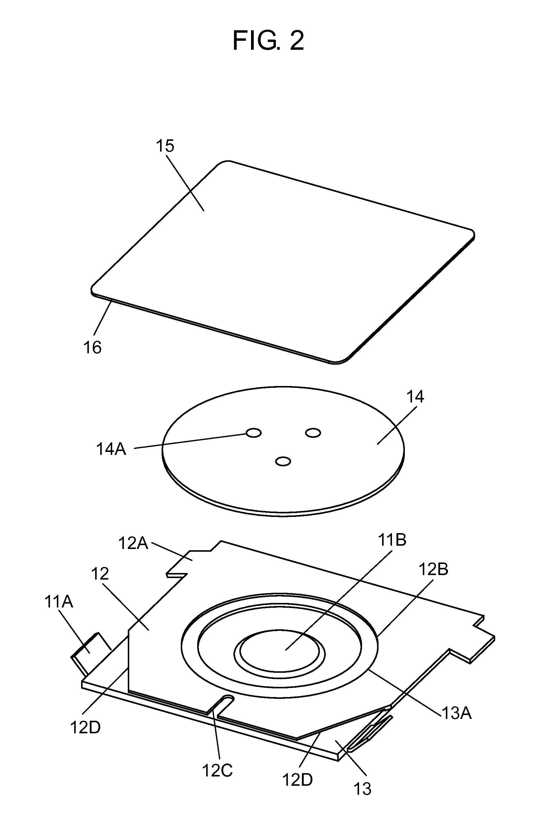
[0023]An exemplary embodiment of the present invention is demonstrated hereinafter with reference to accompanying FIG. 1-FIG. 6. FIG. 1 shows an appearance of a push-on switch in accordance with the embodiment of the present invention. FIG. 2 is an exploded perspective view of the push-on switch in accordance with the embodiment of the present invention. FIG. 3 is a sectional view of the push-on switch in accordance with the embodiment of the present invention. FIG. 4 is a sectional view cut along a place including a slit of the push-on switch in accordance with the embodiment of the present invention. FIG. 5 is a sectional view enlarging the slit of the push-on switch in accordance with the embodiment of the present invention. FIG. 6 is a sectional view of the push-on switch, when it is depressed, in accordance with the embodiment of the present invention.

[0024]Push-on switch 100 includes first contact plate 11, second contact plate 12, spacer 13, movable contact 14, and protective...


PUM


Abstract

A push-on switch includes a first contact plate, second contact plate, spacer, movable contact, and lid. The first plate has a projection at its center and a first terminal at its end. The second plate faces a face of the first contact plate protruding the projection and has an opening at its center and a second terminal at its end. The spacer is interposed between the first second plates for bonding them together. The movable contact is dome-shaped and has a protrusion protruding downward and touches a top face of the second plate. The protrusion faces the projection of the first plate via the opening with a given space therebetween. The lid holds the movable contact and is mounted on the top face of the second plate. A push onto the movable contact reverses the movable contact downward, which allows the protrusion to touch the projection.

Description

FIELD OF INVENTION[0001]The present invention relates to a push-on switch to be used in an operating section of a variety of electronic devices.BACKGROUND OF INVENTION[0002]In recent years, a variety of electronic devices has been downsized, light-weighted, and yet sophisticated. This market trend also requires downsizing of push-on switches to be used at operating sections of the electronic devices.[0003]A conventional push-on switch is described hereinafter with reference to FIG. 8-FIG. 10. FIG. 8 is a sectional view of the conventional push-on switch, and FIG. 9 is an exploded perspective view of the conventional push-on switch. FIG. 10 is a sectional view illustrating the conventional push-on switch depressed. Housing 1 is made of synthetic resin and includes an opening at the top face. On a recessed inner bottom face of housing 1, there are center fixed contact 2 made of metal and two outer fixed contacts 3 made of metal and disposed symmetrically relative to center fixed conta...

Claims


Application Information

Patent Timeline
IPC IPC(8): H01H13/14
CPCH01H13/85H01H2215/018H01H2203/004
Inventor ISHIGAME, AKIRAYANAI, YASUNORI
Owner PANASONIC CORP
Why Eureka
Try Eureka