Power converter apparatus provided with low-pass filter circuit for reducing switching frequency components

Active Publication Date: 2021-09-02
ORMON CORP
View PDF1 Cites 0 Cited by
  • Summary
  • Abstract
  • Description
  • Claims
  • Application Information

AI Technical Summary

Benefits of technology

[0013]Therefore, according to the power converter apparatus of the present invention, it is possible to avoid complication of a circuit config

Problems solved by technology

In a power converter apparatus that performs power conversion by performing on/off control of a switching device, high-frequency switching noise generates due to turning on/off of the switching device because switching control is performed at a switching frequency of 20 kHz or more generally.
As a result, there has be

Method used


Image

  • Power converter apparatus provided with low-pass filter circuit for reducing switching frequency components
  • Power converter apparatus provided with low-pass filter circuit for reducing switching frequency components
  • Power converter apparatus provided with low-pass filter circuit for reducing switching frequency components

Examples


first embodiment

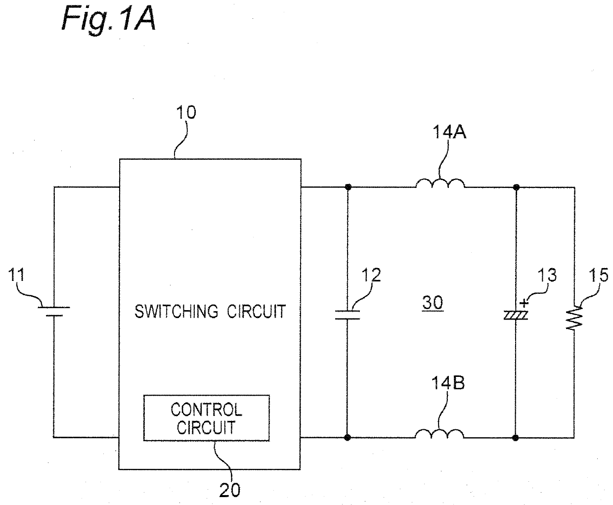
[0028]FIG. 1A is a circuit diagram illustrating a configuration example of a power converter apparatus according to a first embodiment. Referring to FIG. 1A, the power converter apparatus according to the first embodiment is inserted between a direct current (DC) voltage source 11 and a load 15. The power converter apparatus includes a switching circuit 10 and a filter circuit 30. The switching circuit 10 generates an alternating current (AC) voltage by switching the DC voltage from the DC voltage source 11 at a predetermined switching frequency (fSW), and outputs the AC voltage to the filter circuit 30. Next, the filter circuit 30 low-pass filters the AC voltage from the switching circuit to convert the AC voltage into a DC voltage, and outputs the DC voltage to the load 15.

[0029]The switching circuit 10 includes a switching device that switches the DC voltage, and a control circuit 20 that generates a drive signal for driving the switching device with on / off control in a predeterm...

modified embodiment of first embodiment

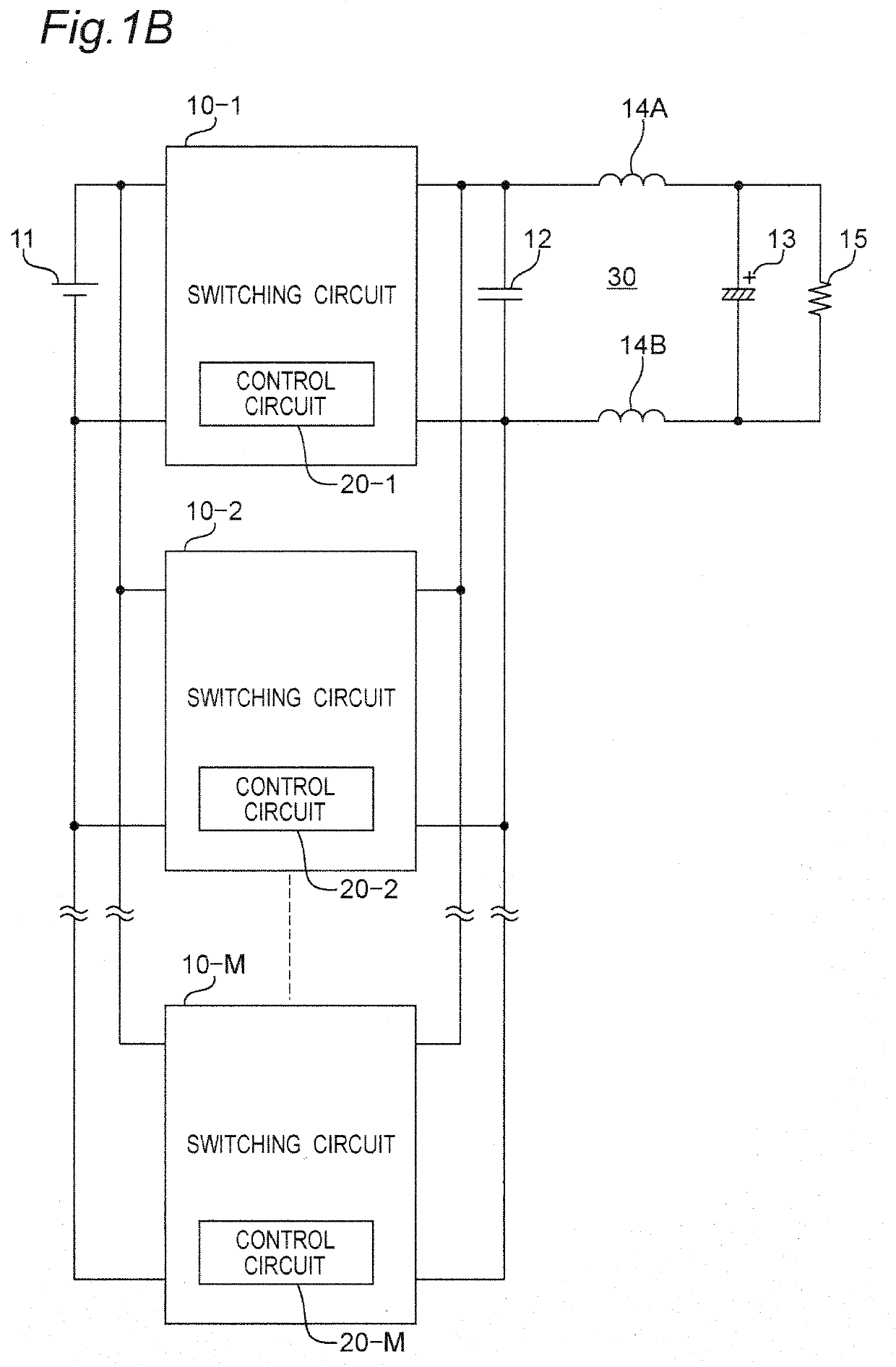
[0036]FIG. 1B is a circuit diagram illustrating a configuration example of a power converter apparatus according to the modified embodiment of the first embodiment. The power converter apparatus of FIG. 1B differs from the power converter apparatus of FIG. 1A in the following point.

[0037](1) Instead of one switching circuit 10, a plurality of M number of switching circuits 10-1 to 10-M is included. Each of the switching circuits 10-1 to 10-M may separately include each of control circuits 20-1 to 20-M that generate a drive signal for driving a switching device, or one control circuit may drive each switching device of a plurality of switching circuits 10-1 to 10-M.

[0038]The power converter apparatus according to the modified embodiment of the first embodiment configured as described above has an action and advantageous effects similar to those of the power converter apparatus according to the first embodiment.

second embodiment

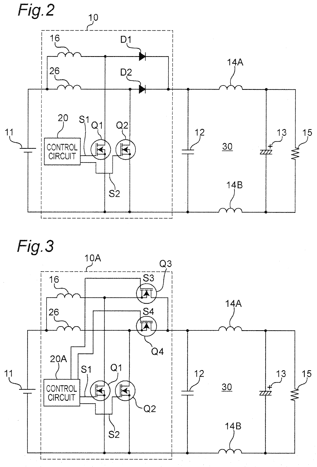
[0039]FIG. 2 is a circuit diagram illustrating a configuration example of an asynchronous power converter apparatus having a step-up function according to a second embodiment. The power converter apparatus according to the second embodiment illustrates a circuit configuration of a switching circuit 10 in detail as compared with the power converter apparatus of FIG. 1, and only differences will be described below.

[0040]Referring to FIG. 2, the switching circuit 10 includes a step-up reactor 16, a switching device Q1 constituted of, for example, a MOSFET, an IGBT, or the like, a diode D1, and a control circuit 20. The DC voltage from the DC voltage source 11 is applied to both of the ends of the drain and source of the switching device Q1 via a reactor 16, and the drain of the switching device Q1 is connected to one end of a bypass capacitor 12 via the diode D1. The control circuit 20 generates a drive signal S1 for driving the switching device Q1 with on / off control in a predetermine...


PUM


Abstract

A power converter apparatus is provided to include a switching circuit, and a filter circuit. The switching circuit generates an AC voltage by switching a DC voltage at a predetermined switching frequency, and the filter circuit converts the AC voltage from the switching circuit into the DC voltage by low-pass filtering the AC voltage. The filter circuit includes first and second bypass capacitors, and an inductor. The first bypass capacitor bypasses noise of a first frequency component of the AC voltage from the switching circuit, and the second bypass capacitor bypasses noise of a second frequency component of the AC voltage from the switching circuit, which is lower than the first frequency component. The inductor is inserted between the first and second bypass capacitors, and the inductance thereof is set so that a resonance frequency of the filter circuit is lower than multiple times the switching frequency by insertion of the inductor.

Description

TECHNICAL FIELD[0001]The present invention relates to a power converter apparatus, such as a DC / DC converter apparatus, for example.BACKGROUND ART[0002]In a power converter apparatus that performs power conversion by performing on / off control of a switching device, high-frequency switching noise generates due to turning on / off of the switching device because switching control is performed at a switching frequency of 20 kHz or more generally. As a result, there has been such a problem that a failure such as malfunction or function stop of electronic equipment occurs.[0003]For example, FIG. 9 illustrates a configuration of a power converter apparatus 101 according to Conventional Example 1 as disclosed in Patent Document 1. Referring to FIG. 9, the power converter apparatus 101 includes a power supply filter circuit 110 and a voltage converter circuit 120. In this case, the power supply filter circuit 110 includes a first filter circuit 111 including a capacitor 111a, and a second fil...

Claims


Application Information

Patent Timeline
IPC IPC(8): H02M1/14H02M3/335H02M1/12
CPCH02M1/14H02M1/126H02M3/33507H02M1/0048H02M3/1584H02M3/1586Y02B70/10H02M3/158
Inventor NOSAKA, NORIYUKINISHIKAWA, TAKEOOKADA, WATARUIWAI, SATOSHIISHII, TAKANORIETO, GUN
Owner ORMON CORP
Why Eureka
Try Eureka