

Sealing apparatus and gas turbine having same
- Summary
- Abstract
- Description
- Claims
- Application Information
AI Technical Summary
Benefits of technology
Problems solved by technology
Method used
Image

Examples
embodiment 1
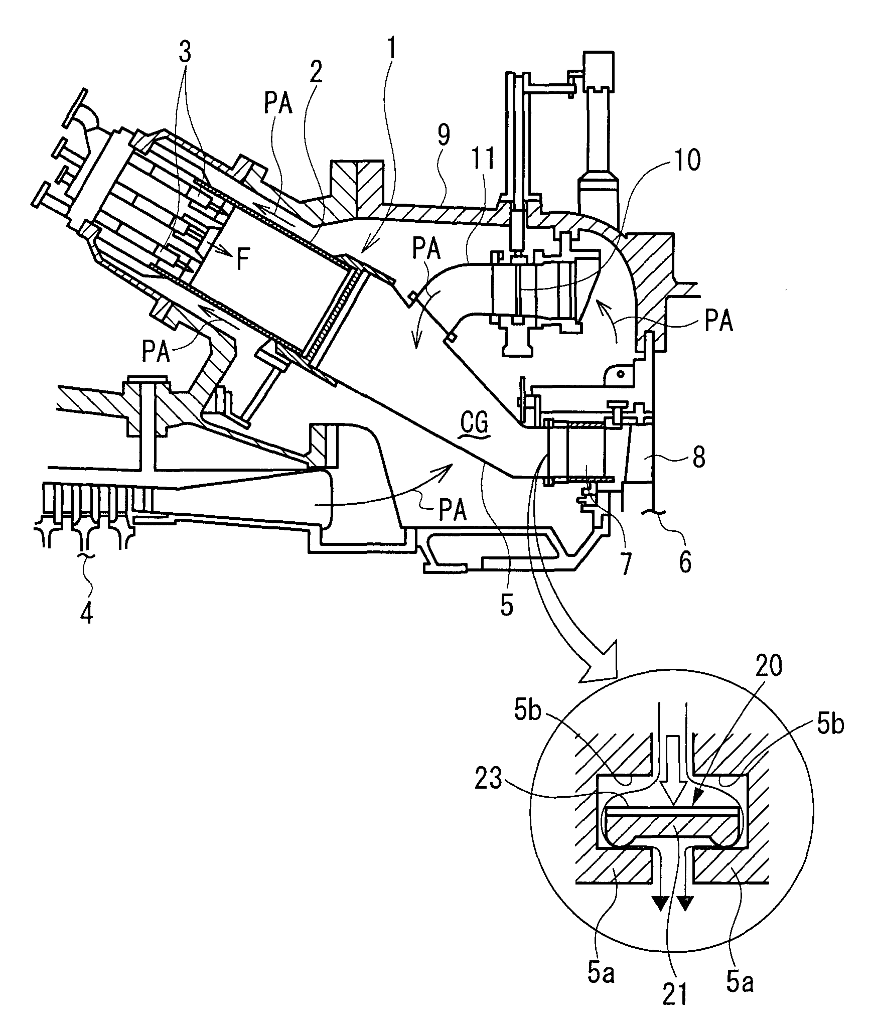
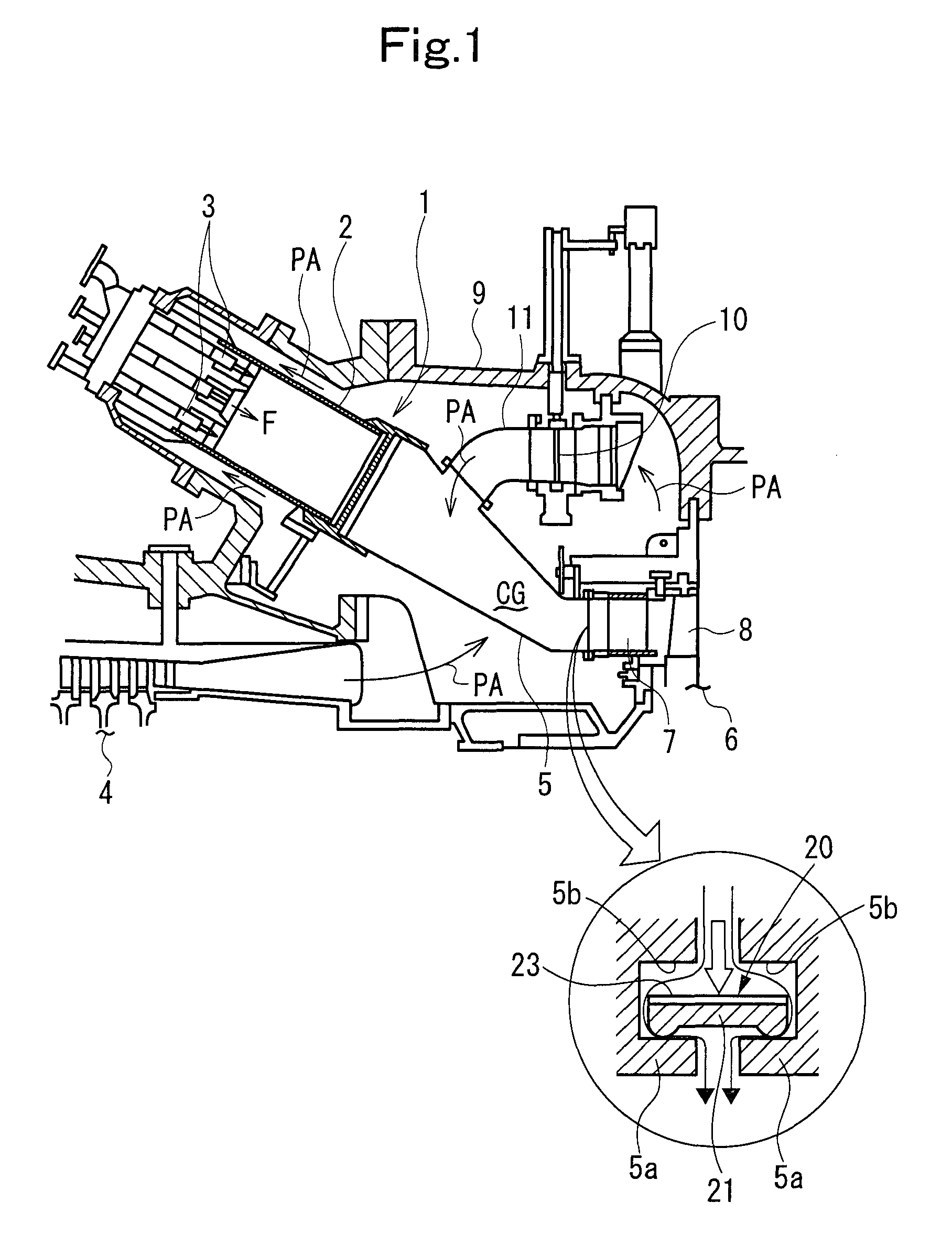
[0030]FIG. 1 is a schematic configurational drawing of essential parts of a gas turbine showing Embodiment 1 of the present invention. FIG. 2 is a perspective view of essential parts of a sealing apparatus in the gas turbine.
[0031]As shown in FIG. 1, a gas turbine has a plurality of (e.g., 16) combustors 1 of a low NOx (premix) type arranged around a main shaft (rotating shaft; not shown). In each combustor 1, a fuel F injected from fuel nozzles 3 provided adjacent to a combustor inner tube 2, and compressed air PA ejected from an air compressor (will hereinafter be referred to simply as a compressor) 4 and introduced to the upstream side of the combustor inner tube 2 are mixed. Then, the mixture is burned in a combustion region on the downstream side of the combustor inner tube 2 or the upstream side of a combustor transition pipe 5, and is introduced into a turbine 6 as a high temperature, high pressure combustion gas CG. In the turbine 6, this combustion gas CG is sequentially pa...
embodiment 2
[0040]FIG. 3 is a plan view of a sealing apparatus showing Embodiment 2 of the present invention.
[0041]This is an embodiment in which the seal pieces 21 in Embodiment 1 are arranged symmetrically on both surfaces of the sheet 23. The sealing apparatus according to this embodiment can be used as a sealing apparatus between the components when the flowing direction of leaking air is reversed in the seal groove 5b.
embodiment 3
[0042]FIG. 4 is a configurational drawing of a sealing apparatus showing Embodiment 3 of the present invention.
[0043]This is an embodiment in which seal pieces 21A as in Embodiment 1, formed by press-working to have sealing ridges 24A of a semi-annular cross section, are laminated in a superposed manner by spot welding W, and a plurality of the resulting laminates are tied (connected) together in the longitudinal direction by two wires 25. That is, each wire 25 is inserted into the circular hole formed by the two sealing ridges 24A opposing each other.
[0044]According to the present embodiment, like Embodiment 1, the sealing apparatus 20 can be realized which has a small number of the components, whose production is easy, and which is wear resistant. Thus, it has high sealing performance, and can achieve cost reduction. Since the core material is the wire 25, moreover, moderate flexibility can be imparted, and assembly characteristics can also be enhanced.
PUM
 Abstract
Description
Claims
Application Information