[0005]A dynamic alignment
monitoring system is described for use with an on-vehicle disk brake lathe that employs a dynamic alignment system using a trial-and-error scheme to adjust the alignment, such as described in U.S. Pat. No. 6,101,911 and incorporated herein by reference. The system can optionally be provided with an operator intervention option that allows the operator to selectively stop further adjustment of the alignment when appropriate. Such trial-and-error systems are felt to provide a benefit over determinative lathe systems such as taught in U.S. Pat. No. 6,813,979 that require the system be initialized by the operator, which makes the alignment
process time consuming and also subject to operator error. The dynamic alignment system of the present invention provides an
advantage over earlier trial-and-error systems in that it provides the operator with a real-time representation of current state of misalignment during the alignment process.
[0006]The system of the present invention monitors misalignment between a lathe axis and a brake disk axis with the use of a high sensitivity
angular velocity or
angular acceleration sensor (hereafter referred to as an
angular rate sensor, whether measuring
angular velocity or
angular acceleration). An angular rate sensor is employed because it ignores any motion other than rotation and is not dependent on being mounted at a particular position on the lathe body. The employment of a high sensitivity angular rate sensor overcomes some of the limitations of earlier accelerometers, such as the limitations pointed out in the '979 patent, and assures sufficient responsiveness to allow derivation of an accurate representation of the lateral runout that would result from
machining the brake disk under the current condition of misalignment. These high sensitively angular rate sensors, when used with other features of the system, allow an operator to monitor the misalignment in real time, and in some embodiments provide the operator an option to discontinue further automatic adjustment of the alignment when, in the operator's judgement, further adjustment is not necessary. When such an option is present, it allows the operator to selectively stop the automatic alignment process can reduce the time for the alignment.
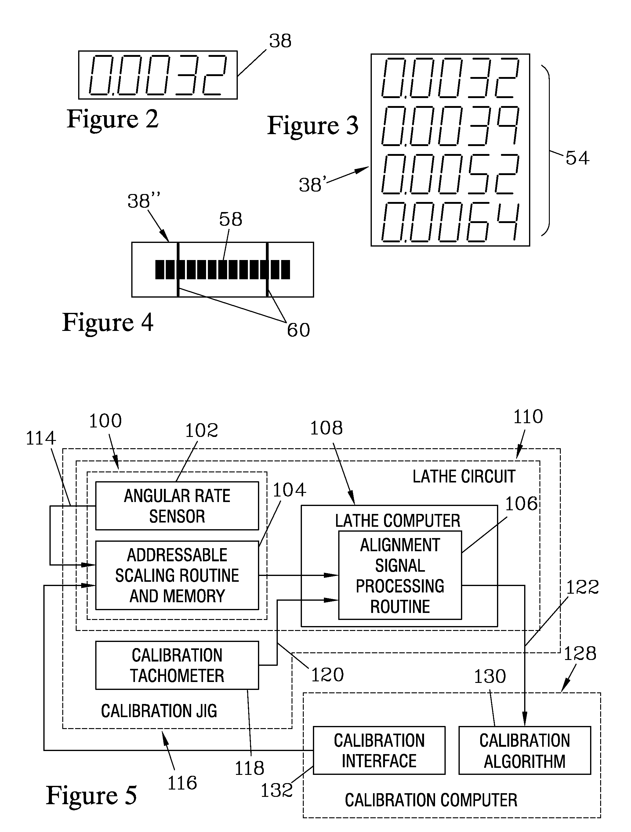
[0007]High sensitivity angular rate sensors as defined in the present application are sensors having a very high degree of
repeatability in their response, and where the response can be accurately correlated to changes in the
angular velocity or
angular acceleration. Angular rate sensors generally do not do not provide this combination of properties; however, it is possible to provide an improved sensor by preselecting an angular rate sensor that provides a high degree of
repeatability (low standard deviation σ in its response) and
coupling the selected sensor to an addressable scaling routine which can be calibrated to provide an individually scaled output indicative of the lateral runout that the sensor is monitoring.
[0009]The selection of an angular rate sensor having a low standard deviation allows the response of the sensor to closely track the angular rate as a function of time, such that the output
signal from any sensor falling within these limitations provides a phase-accurate depiction of the angular rate over time where the amplitude is closely proportional to the angular rate. If the frequency of the rotation is known, the amplitude for the angular rate can then be correlated to a
maximum displacement corresponding to the angular motion; the frequency is typically determined by monitoring a
tachometer that responds to the rotation of a spindle of the brake lathe.
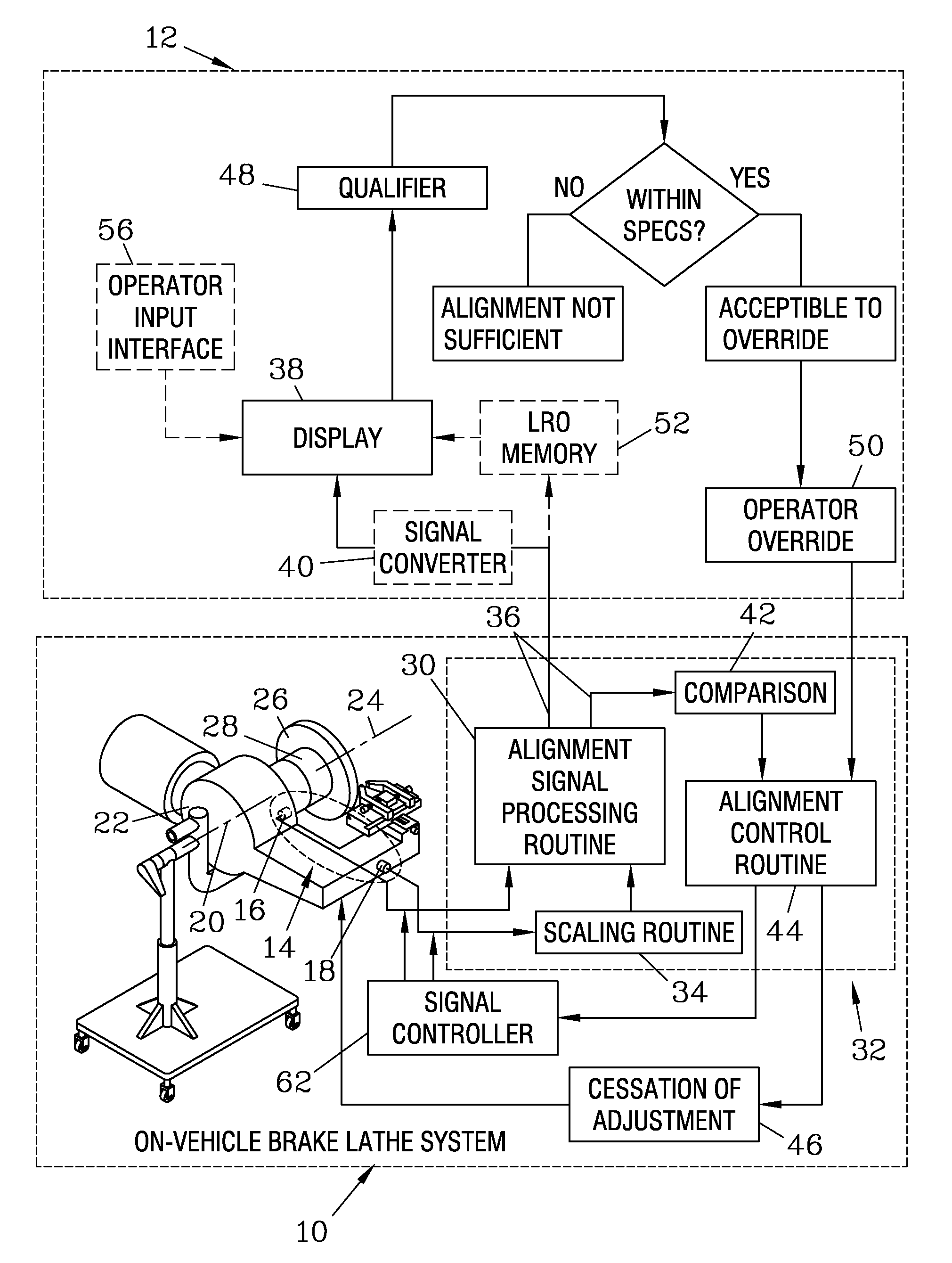
[0014]The dynamic alignment
monitoring system of the present invention includes an alignment control routine and dynamic alignment mechanism, which can be operated in a conventional trial-and-error manner to automatically reduce the misalignment by determining whether adjustments act to increase or decrease the misalignment and making further adjustments accordingly until the misalignment has been reduced to a specified degree as indicated by the character of the
signal output by the alignment
signal processing routine. While such automatic alignment could be performed using output of the alignment
signal processing routine which is not scaled so as to be proportional to the lateral runout, the high sensitivity angular rate sensor that is employed in the present monitoring and intervention system can allow the
signal processing routine to output an accurately proportional derived LRO value that should provide greater assurance that the automatic alignment procedure results in a sufficient reduction in the misalignment that the machined disk will meet manufacturer specifications, as well as possibly speeding alignment times by providing a more accurate basis for evaluating whether adjustments act to increase or decrease the misalignment. In any case, while the alignment reduction can be performed automatically as in earlier systems, some embodiments of the system of the present invention allow the operator to selectively interrupt the automatic process when appropriate to allow
machining the brake disk without waiting for further adjustments to be made.
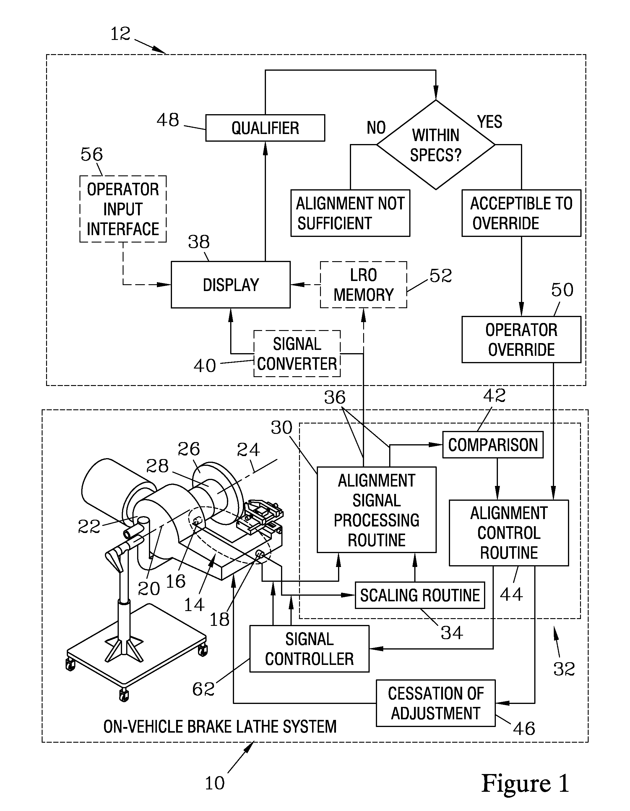
[0016]When the system is designed to allow the operator to manually cause the adjustment procedure to be discontinued when the displayed state of alignment indicates, in view of the operator's judgement, that such premature cessation of the adjustment is desirable, an operator override is provided to form an alignment monitoring and intervention system. The monitoring and intervention system can also present additional information on the display to assist the operator in interpreting the displayed representation of the derived LRO value to determine when it is appropriate to discontinue the alignment process. The display can present a target value for the lateral runout entered by the operator, such information being available from the vehicle manufacturer. In more comprehensive monitoring and intervention systems, the system communicates with a
database of specification information for the available vehicle models and the monitoring and intervention system is provided with an
operator interface which allows the operator to select information relevant to the vehicle on which the brake disk is to be serviced from the
database. In such cases, the monitoring and intervention system can use the vehicle / wheel information to select appropriate specification information from the
database and provide a display of a target lateral runout value that is appropriate for the particular vehicle and wheel position to assist the operator in making the decision as to whether to take control based on a comparison of the current derived LRO value to the target value.

