Variable speed power generator having two induction generators on a common shaft

a variable speed power generator and induction generator technology, applied in the field of induction machines, can solve the problems of significant maintenance costs and problems, less commercial significance of induction generators, and low importance of power generation,

Inactive Publication Date: 2009-05-14
VARISPEED ELECTRIC MOTORS
View PDF16 Cites 53 Cited by
  • Summary
  • Abstract
  • Description
  • Claims
  • Application Information

AI Technical Summary

Problems solved by technology

Induction machines are well known; however for a long time it has been considered that synchronous machines were much better for generating alternating current, and the induction generator has been considered less commercially significant and its importance for power generation downplayed.
However, when variable speed energy sources are to be integrated with large scale supplies and connected to large scale grids, sophisticated and expensive electronic controls are required.
There are very significant maintenance costs and problems associated with brushes and sliprings for a generator which is located at the top of a high tower, where such a generator is usually located in order to generate maximum power from a large rotating wind-driven propeller or prime mover.
(Another form of a doubly-fed machine which is not generally satisfactory in a power generation application has TWO stator windings which interact with each other and upon the conductors of a common rotor winding.)
However a full reduction gearbox adds a very significant mass to the system, which is undesirable in terms of cost and logistics when located at the top of a high tower.
Alternatively conventional synchronous generators may be used, however these are fundamentally constant speed devices and can only be used in wind applications if the output is rectified and then converted back to mains frequency.
Whilst this eliminates the necessity for a gear box, the high cost of a full power (PWM) inverter makes conventional synchronous generators very expensive.
This system introduces assembly and mechanical difficulties.
However, such a machine does not of itself constitute a substitute for other forms of variable speed generators, including the doubly-fed induction generator and the permanent magnet synchronous generator used in conjunction with a full power inverter referred to above.

Method used


Image

  • Variable speed power generator having two induction generators on a common shaft
  • Variable speed power generator having two induction generators on a common shaft
  • Variable speed power generator having two induction generators on a common shaft

Examples


Embodiment Construction

[0027]In order to enable a clearer understanding of the invention, drawings illustrating example embodiments are attached, and in those drawings:

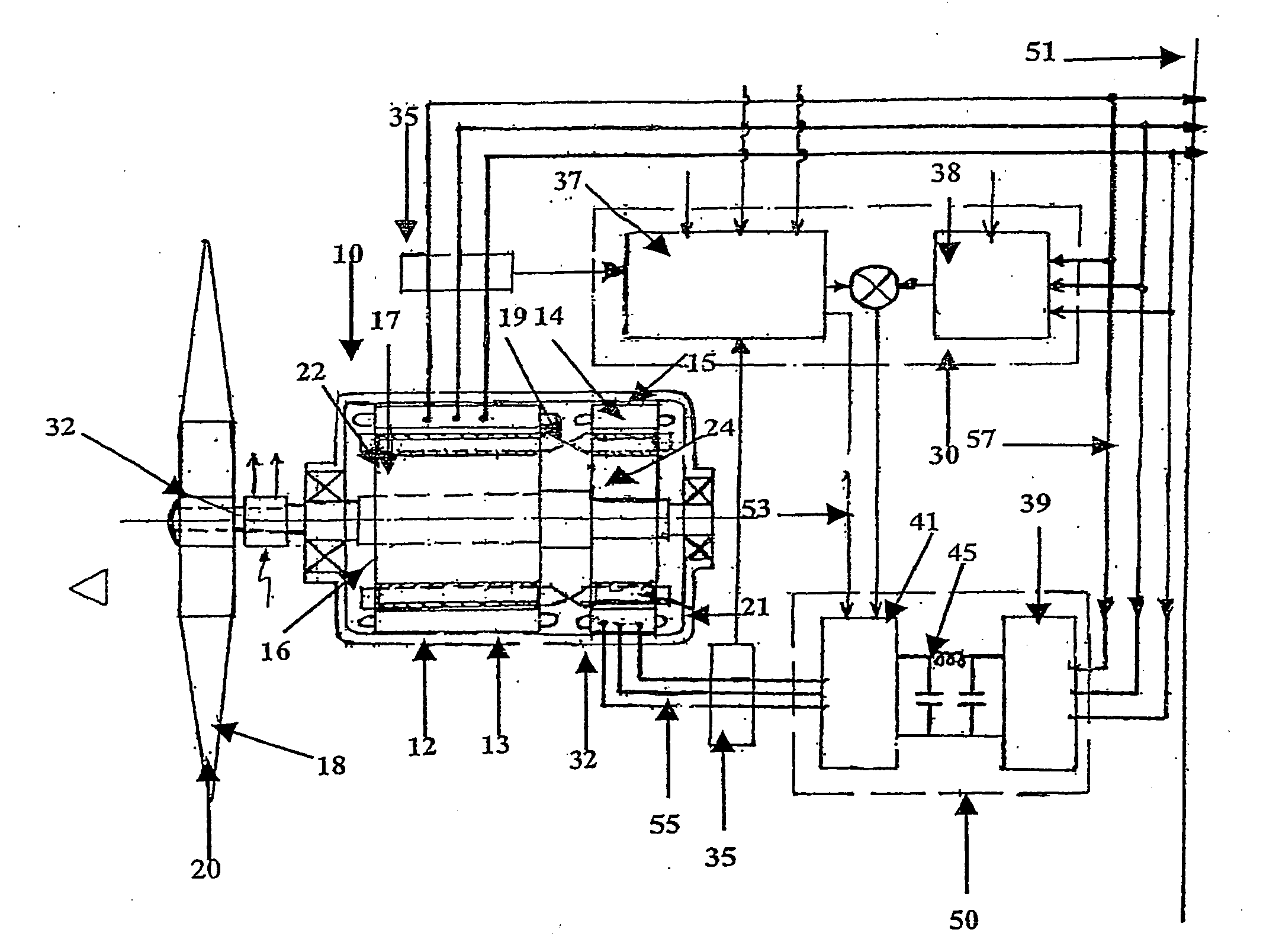
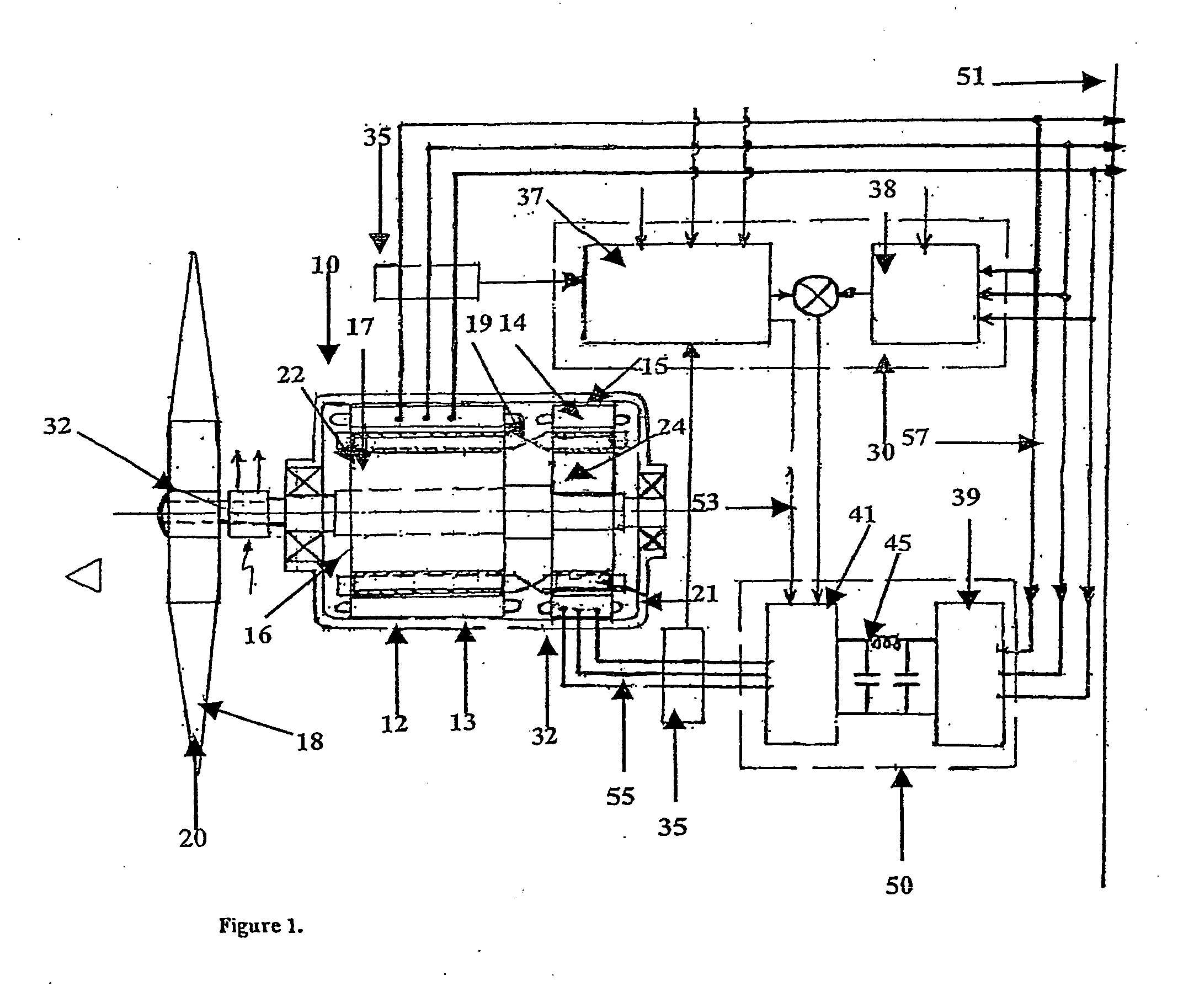
[0028]FIG. 1 is a basic connections diagram of the wind energy power generation system;

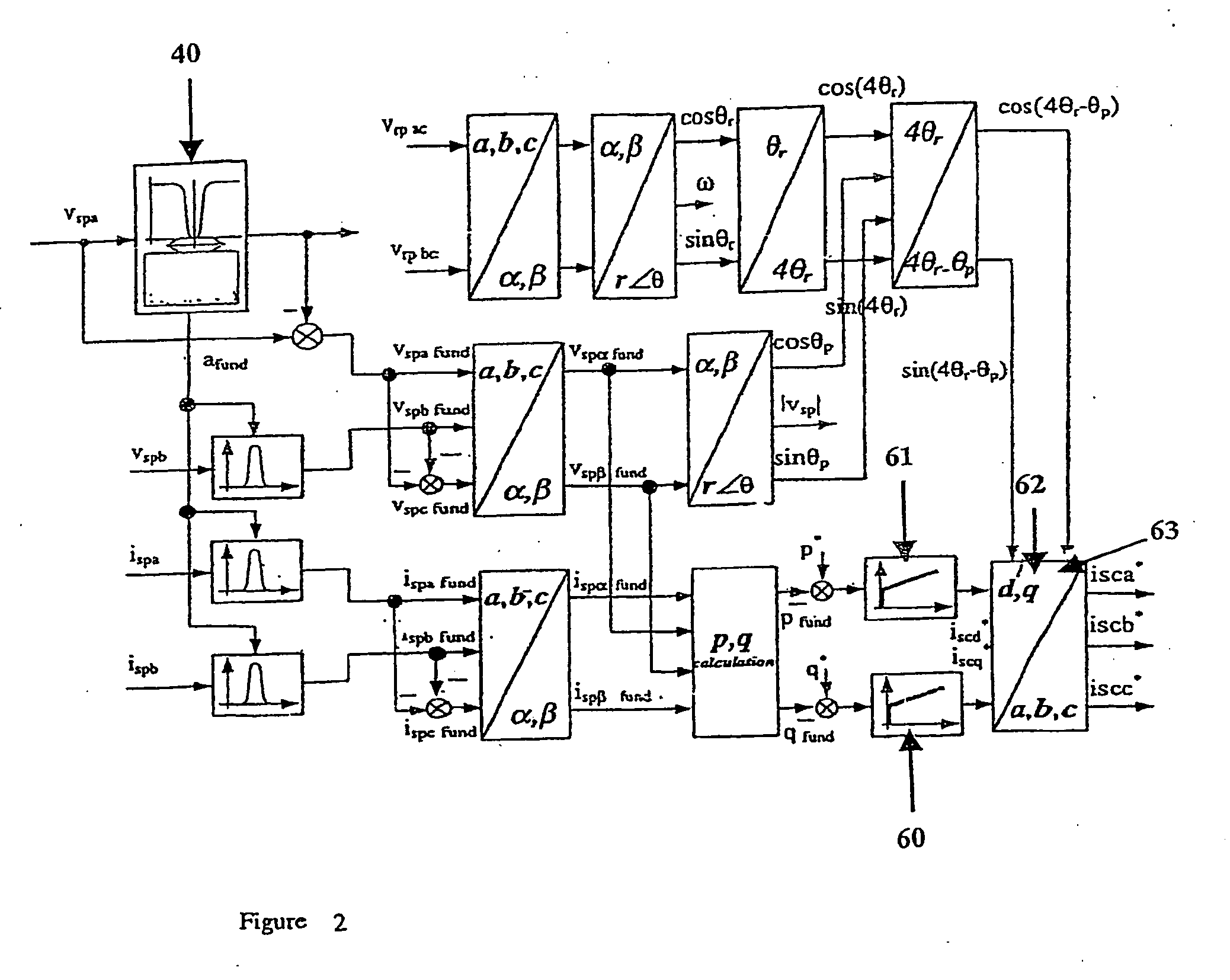
[0029]FIG. 2 is a block diagram of the control system associated with the generation system.

[0030]Referring to FIG. 1 there is shown a power generator generally indicated at 10 in the form of a primary induction generator 12 and a secondary or control induction generator 14 mounted on a common shaft 16 for rotation thereabout. A prime mover 18 in the form of a wind turbine 20 is also provided, mounted on the common shaft 16. The primary and secondary induction generators 12, 14 employ rotors 22, 24 of the squirrel cage type, having a laminated structure 17 as well as rotor bars 19, 23 and windings 21, 25. The bars 19, 23 of both rotors 22, 24 are insulated from the corresponding laminated structure 17. This electrical isolation is achieved in this embodim...


PUM


Abstract

A variable speed power generator system, includes a primary power induction generator (12), a secondary control induction (14), each of the induction generators having a rotor (22, 24) mounted so as to be rotated by a common shaft (16) of a variable speed prime mover (20), an inverter (50) connected to the stator (15) of the secondary control induction generator, a controller (30) connected to the inverter controls the output of the inverter, output of the primary induction generator is connected to the grid (51), controller provides output signal to the inverter based on selected inputs to the controller so that the output of the primary induction generator matches the active and reactive power requirements of the grid. An induction machine which includes a rotor having laminations and insulated cage bars, the bars being electrically isolated from on another as well as electrically insulated from the laminations.

Description

FIELD OF THE INVENTION[0001]The present invention relates generally to induction machines, in particular concerning power generation from variable speed inputs, such as for example those found in wind energy generation, hydroelectric power generation and tidal power generation. Although it will be convenient to hereinafter describe the invention with reference to wind turbine applications, it is to be understood that this is not to be taken as a limitation of the scope of the invention.BACKGROUND TO THE INVENTION[0002]Induction machines are well known; however for a long time it has been considered that synchronous machines were much better for generating alternating current, and the induction generator has been considered less commercially significant and its importance for power generation downplayed.[0003]When variable speed energy sources are operating independently of other energy systems, electricity of reliable and usable frequency and current can be obtained effectively and ...

Claims


Application Information

Patent Timeline
Patent Type & Authority Applications(United States)
IPC IPC(8): H02P9/30H02K16/00H02P9/14F03B15/00F03D7/02F03D9/00H02J3/40H02K7/18H02K17/42H02P9/00
CPCF03B15/00H02P2101/15F03D9/003F05B2270/1016F05B2270/1041H02J3/40H02K7/1823H02K16/00H02K17/42H02P9/007Y02E10/226Y02E10/723Y02E10/725Y02E10/763H02K7/1838H02J3/382H02J3/386F03D7/0272F03D9/255F03D15/10H02J2300/28H02J2300/20H02J3/381Y02E10/20Y02E10/72Y02E10/76
Inventor RICKARD, JUSTIN ROALD
Owner VARISPEED ELECTRIC MOTORS
Why Eureka
Try Eureka