Insulated power transfer device

a technology of power transfer device and insulated cable, which is applied in the direction of electric variable regulation, process and machine control, instruments, etc., can solve the problems of device also becoming more costly, no longer a response to demand, energy loss, etc., and achieves simple series connection, improved converter efficiency, and better performance characteristics.

Active Publication Date: 2009-05-21
THALES SA
View PDF24 Cites 31 Cited by
  • Summary
  • Abstract
  • Description
  • Claims
  • Application Information

AI Technical Summary

Benefits of technology

[0017]To best optimize the use of the magnetic coupler on the secondary and the switched-mode converter on the primary, the idea on which the invention is based is to modify the structure of the converter and of the coupler, notably to obtain a better efficiency of the converter, soft switching, at zero voltage at their terminals, and therefore without stress for the components, and on opening of the switches of the primary, a zero current in the leakage inductance. The invention goes beyond a simple series connection of a switched-mode converter and a magnetic coupler with regulation. A hybridation of both the power and the control law is produced, which makes it possible to obtain better performance characteristics, with a smaller material volume, and therefore with smaller components, notably less silicon surface area, a less heavy device and less dissipated heat. The switched-mode converter makes it possible to obtain a fixed optimal voltage that is independent of the variations of the input voltage, and the regulation of the coupler makes it possible to obtain on the secondary the output voltage that is required according to the output load.

Problems solved by technology

However, passing the power through the various components causes energy losses, notably in the diode 6 of the boost converter.
There is then no longer a response to the demand for the requisite small footprint, and the device also becomes more costly.
Another drawback is that the switch 7 of the boost converter is then controlled by hard switching, that is, when the voltage is not zero at the terminals of the switch at the time of the switching phases.

Method used


Image

  • Insulated power transfer device
  • Insulated power transfer device
  • Insulated power transfer device

Examples


Embodiment Construction

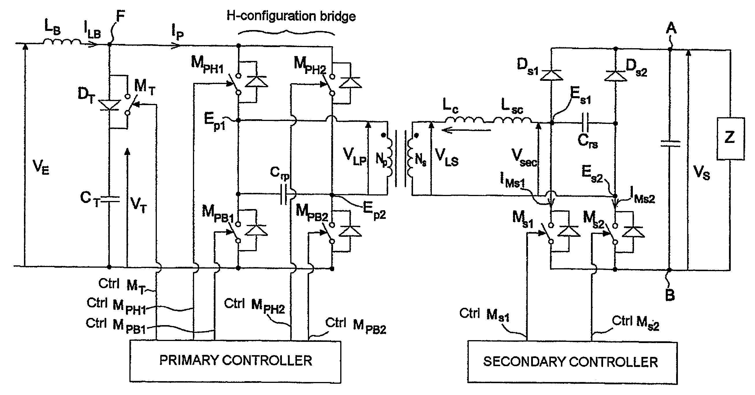
[0042]FIG. 2 shows a circuit diagram of an insulated power transfer device connected to an output load Z according to the invention. The load Z is connected between a first output terminal A and a second output terminal B. The device comprises a DC voltage source VE and a magnetic coupler CM which comprises:[0043]a transformer comprising, between two primary terminals Ep1, Ep2, a primary winding Np, and between two secondary terminals Es1, Es2 a secondary winding Ns in series with a coupling inductance Lc, said coupling inductance comprising at least the leakage inductance Lf of said transformer;[0044]a rectifier bridge comprising two diodes Ds1, Ds2, each diode connected between a respective secondary terminal Es1, Es2 and the first output terminal A and two controlled switches Ms1, Ms2, each switch being connected between a respective secondary terminal Es1, Es2 and the second output terminal B.

[0045]The insulated power transfer device according to the invention also comprises, on...


PUM


Abstract

An insulated transfer device with particular topology, comprising on the primary, a switched-mode voltage step-up circuit, with a step-up inductance (LB) and an active buffer stage (DT, MT, CT) supplying a peak voltage greater than the peak voltage supplied by the input voltage source (vE) and two pairs of controlled switches controlling the application of the voltage supplied by the switched-mode voltage step-up circuit, to the terminals (Ep1, Ep2) of the primary winding and to the secondary, a full-wave rectifier with diodes (Ds1, Ds2) and controlled switches (Ms1, Ms2). On the primary, the voltage at the terminals of the capacitor CT of the active buffer stage used to apply a controlled AC voltage between the terminals Ep1 and Ep2 is regulated by controlling the time for which the controlled switches of the pairs are simultaneously in the closed state. On the secondary, VS is regulated by controlling the time for which the secondary switches are simultaneously in the closed state.

Description

CROSS-REFERENCE TO RELATED APPLICATIONS[0001]The present Application is based on International Application No. PCT / EP2007 / 054122, filed on Apr. 26, 2007, which in turn corresponds to French Application No. 0603731 filed on Apr. 26, 2006, and priority is hereby claimed under 35 USC §119 based on these applications. Each of these applications are hereby incorporated by reference in their entirety into the present application.FIELD OF THE INVENTION[0002]The present invention relates to an improved insulated power transfer device.BACKGROUND OF THE INVENTION[0003]For certain applications, and specifically in the field of avionics, there is a need for power transfer devices that offer the following qualities:[0004]a high and electrically insulated output voltage;[0005]a high input dynamic range, preferably greater than two (ratio between maximum input voltage and minimum input voltage);[0006]a transformation ratio between the value of the output voltage and the high input voltage;[0007]an...

Claims


Application Information

Patent Timeline
Patent Type & Authority Applications(United States)
IPC IPC(8): H02M3/335
CPCH02M3/33576H02M1/0085
Inventor TAURAND, CHRISTOPHEVIRE, GUILLAUME
Owner THALES SA
Why Eureka
Try Eureka