Transition duct assembly

a transition duct and assembly technology, applied in the direction of machines/engines, stators, liquid fuel engines, etc., can solve the problems of high thermal and mechanical stress in the transition duct assembly, excessive wear or failure of components, and many assembly problems

Active Publication Date: 2009-06-11
ANSALDO ENERGIA SWITZERLAND AG
View PDF12 Cites 46 Cited by
  • Summary
  • Abstract
  • Description
  • Claims
  • Application Information

AI Technical Summary

Problems solved by technology

A change in the radial profile can cause numerous assembly issues between the combustor and the turbine.
Also, such a change in geometry for the transition duct assembly, which is operating at extremely high temperatures can create high thermal and mechanical stresses in the transition duct assembly.
When a component has a natural frequency that coincides ...

Method used


Image

  • Transition duct assembly
  • Transition duct assembly
  • Transition duct assembly

Examples


Embodiment Construction

[0018]The subject matter of the present invention is described with specificity herein to meet statutory requirements. However, the description itself is not intended to limit the scope of this patent. Rather, the inventors have contemplated that the claimed subject matter might also be embodied in other ways, to include different components, combinations of components, steps, or combinations of steps similar to the ones described in this document, in conjunction with other present or future technologies.

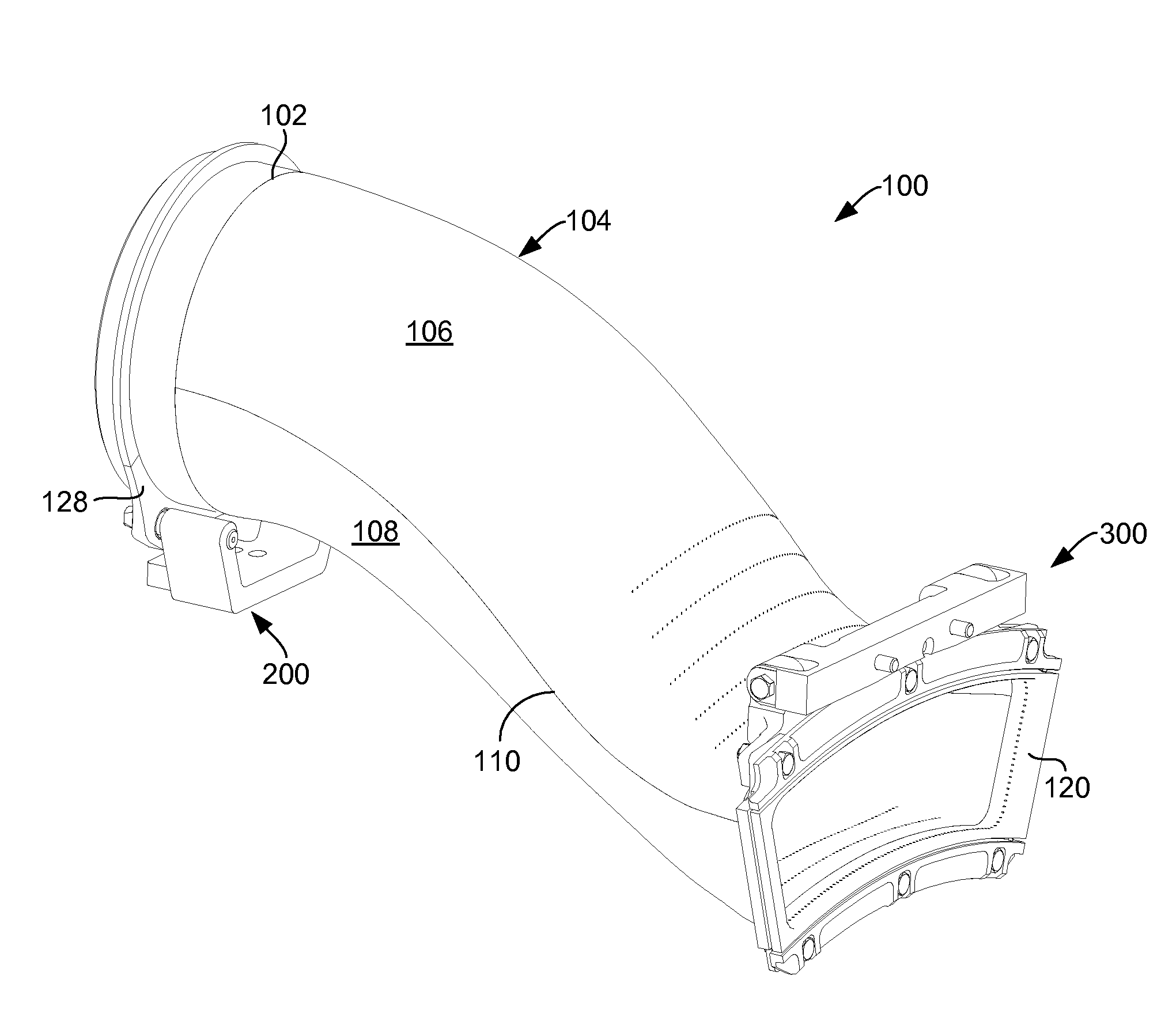
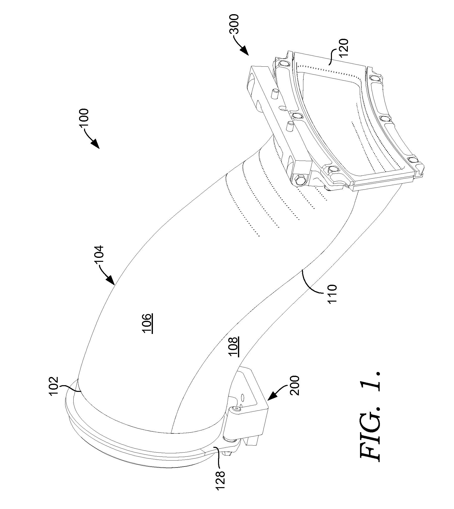
[0019]Referring initially to FIG. 1, a transition duct assembly 100 in accordance with an embodiment of the present invention is shown. The transition duct assembly 100 includes a generally cylindrical inlet sleeve 102 and a panel assembly 104. The inlet sleeve 102 has an inner diameter and an outer diameter, while the panel assembly 104 extends from the inlet sleeve 102 at the inner and outer diameter thereof via a first panel 106 and a second panel 108, as can be seen with additio...


PUM


Abstract

A transition duct assembly with a thermally free aft frame and mounting system for use in a gas turbine engine are disclosed. The aft frame is capable of adjusting to thermal gradients while the mounting system provides for at least transverse movement of the transition duct during engine assembly. The mounting system also provides a means for raising the natural frequency of the transition duct outside of the engine's dynamic excitation ranges.

Description

CROSS-REFERENCE TO RELATED APPLICATIONS[0001]This application claims priority to U.S. Provisional Application Ser. No. 61 / 012,636, filed on Dec. 10, 2007.TECHNICAL FIELD[0002]The present invention relates to gas turbine engines. More particularly, embodiments of the present invention relate to an apparatus and method for lowering thermal and mechanical stresses in a transition duct assembly while also providing a transition duct assembly with a natural frequencies outside of critical engine frequencies.BACKGROUND OF THE INVENTION[0003]Gas turbine engines operate to produce mechanical work or thrust. Specifically, land-based gas turbine engines typically have a generator coupled thereto for the purposes of generating electricity. A gas turbine engine comprises at least a compressor section having a series of rotating compressor blades. The compressor receives air from an engine inlet. The air passes through the compressor, which causes the pressure of the air to increase. The compres...

Claims


Application Information

Patent Timeline
IPC IPC(8): F02C7/00
CPCF01D9/023F05D2260/96F05D2230/642F01D25/28
Inventor RIZKALLA, HANYJORGENSEN, STEPHEN W.STUTTAFORD, PETERRICKLIN, PLAZIHENRIQUEZ, DAVID JOHN
Owner ANSALDO ENERGIA SWITZERLAND AG
Why Eureka
Try Eureka