
Tube conveyor with sealing belt edges

a conveyor and tube technology, applied in the direction of conveyor parts, conveyor-ways, loading/unloading, etc., can solve the problems of high potential for grain or seed to fall off the edge of the belt, severe damage to the grain and seed, and potential damage to the belt edge, and is especially undesirable with expensive cargo

Active Publication Date: 2010-04-06
UNVERFERTH MFG
View PDF14 Cites 19 Cited by
  • Summary
  • Abstract
  • Description
  • Claims
  • Application Information

AI Technical Summary

Benefits of technology

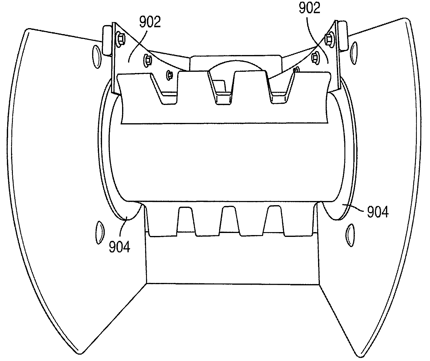
[0008]According to an embodiment of the present invention, a belt driven conveyor is provided having an intake end having a first roller or pulley, a discharge end having a second roller or pulley, a tube section connected the intake end and the discharge end, and a conveyor belt installed about the first and second rollers or pulleys. A motor or other drive means can be provided for rotating one or both of the rollers or pulleys or otherwise moving the belt to carry cargo from the intake end to the discharge end. Seal means are provided at the discharge end for preventing cargo from moving off the side of the belt.
[0011]According to an embodiment of the present invention, teeth members or cleats are provided on the belt at selected positions for improving movement of grain.
[0013]According to another embodiment of the present invention, brush seals may be employed at the intake end of the conveyor to prevent cargo from moving off the end of the belt.

Problems solved by technology

When used with grain or seed, however, this configuration suffers from the problem that when the belt flattens out on the discharge end of the conveyor, there is great potential for grain or seed to fall off the edge of the belt, especially on steep inclines.
The grain or seed that falls over the edge can collect between the upper and lower portions of the belt or get “sandwiched” between the end pulley, the belt and the conveyor housing resulting in severe damage to the grain and seed, and potential damage to the belt.
This is especially undesirable with expensive cargo such as seed.

Method used


Image

  • Tube conveyor with sealing belt edges
  • Tube conveyor with sealing belt edges
  • Tube conveyor with sealing belt edges

Examples


Embodiment Construction

[0026]While the present invention may be embodied in many different forms, a number of illustrative embodiments are described herein with the understanding that the present disclosure is to be considered as providing examples of the principles of the invention and such examples are not intended to limit the invention to preferred embodiments described herein and / or illustrated herein.

[0027]In embodiments of the present invention, the novel conveyor pivot system can be implemented with seed carrier or seeding machines. The following section describes non-limiting examples of illustrative seeding equipment according to embodiments of the present invention. It should be appreciated that the following examples are provided for illustration and the present invention is not intended to be limited to the embodiments described herein.

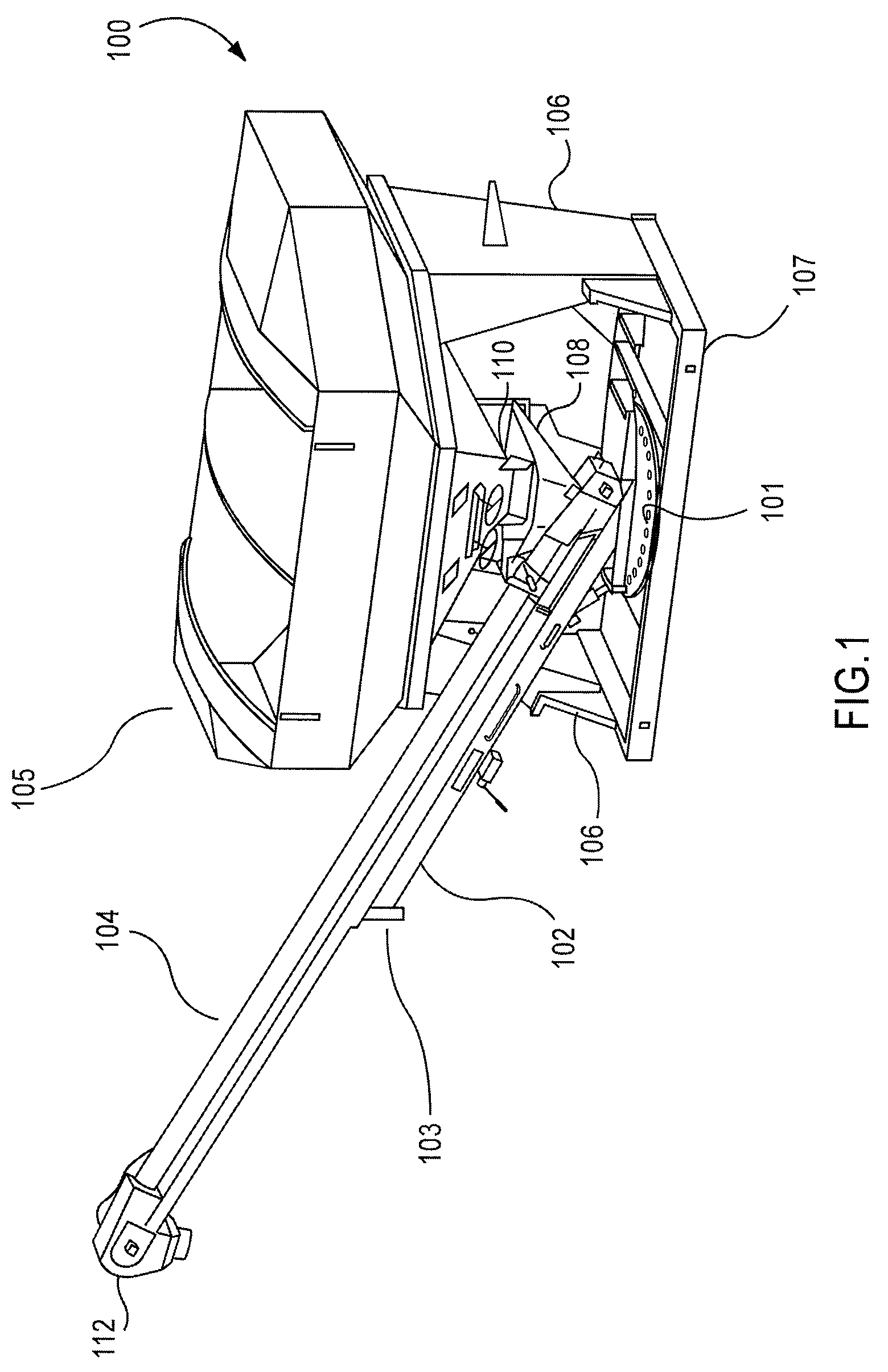
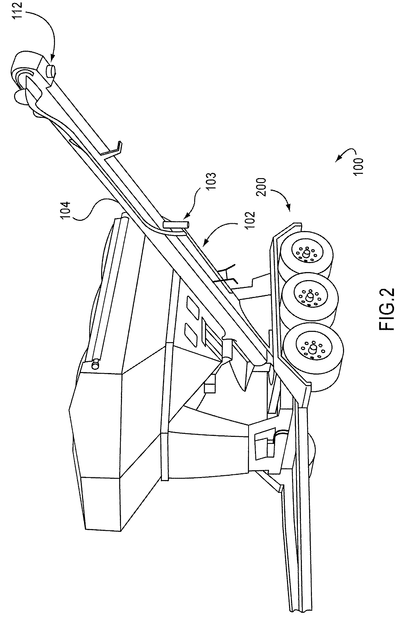
[0028]FIG. 1 is a diagram depicting a seed carrier having a tube conveyor according to an embodiment of the present invention. The seed carrier 100 includes a ...


PUM


Abstract

A tubular conveyor for conveying grain or seed includes an intake end having a first roller and a discharge end having a second roller. A tubular portion is disposed between the intake end and the discharge end. A continuous flexible conveyor belt is coupled with the first and second rollers. Seal means are provided for sealing edges of the conveyor belt at a point approximately where the conveyor belt meets at least one of the first and second rollers.

Description

CROSS-REFERENCE TO RELATED APPLICATION[0001]The present application claims priority to Provisional Patent Application Ser. No. 60 / 901,326 filed on Feb. 15, 2007, the entire disclosure of which is incorporated herein by reference.BACKGROUND OF THE INVENTION[0002]1. Field of the Invention[0003]The present invention relates generally to a conveyor system for a grain or seed carrier. More particularly, the present invention relates to a belt driven tubular conveyor system having sealed edges at the rollers.[0004]2. Description of the Related Art[0005]Conveyor systems for moving grain, seed, etc. are well known. Auger systems are used to rapidly move grain such as feed or the like, while belt driven conveyors are often used for moving more expensive payload, such as seed. Tube conveyors have wide use in many applications, including in agriculture, where they are used to convey seed or grain from holding containers to seeding equipment or other containers.[0006]Belt driven tube conveyors ...

Claims


Application Information

Patent Timeline
Patent Type & Authority Patents(United States)
IPC IPC(8): B65G21/20
CPCB65G15/08B65G15/42B65G65/42B65G41/005B65G21/2081
Inventor SMITH, DAVID RICHARDHILVERS, MICHAEL J.PETERSEN, BRIAN JAMES
Owner UNVERFERTH MFG
Learn More