Tie plate singularization device

a technology of singularization device and tie plate, which is applied in the direction of railway track construction, railway tracks, construction, etc., can solve the problems of increasing labor costs, work-related injuries, and incompatibility with rapid, efficient railroad tie replacement, and achieve the effect of enhancing the movement of the tie pla

Inactive Publication Date: 2011-05-05
TAYLOR TIMOTHY CHARLES
View PDF29 Cites 22 Cited by
  • Summary
  • Abstract
  • Description
  • Claims
  • Application Information

AI Technical Summary

Benefits of technology

[0012]A particular object of this invention is to provide a device, as aforesaid, which deposits the tie plates o...

Problems solved by technology

Obviously, this is a very labor intensive operation which increased labor costs, work-related injuries and was not compatible with rapid, efficient railroad tie replacement.
Such devices were relatively complex mechanisms...

Method used


Image

  • Tie plate singularization device
  • Tie plate singularization device
  • Tie plate singularization device

Examples


Embodiment Construction

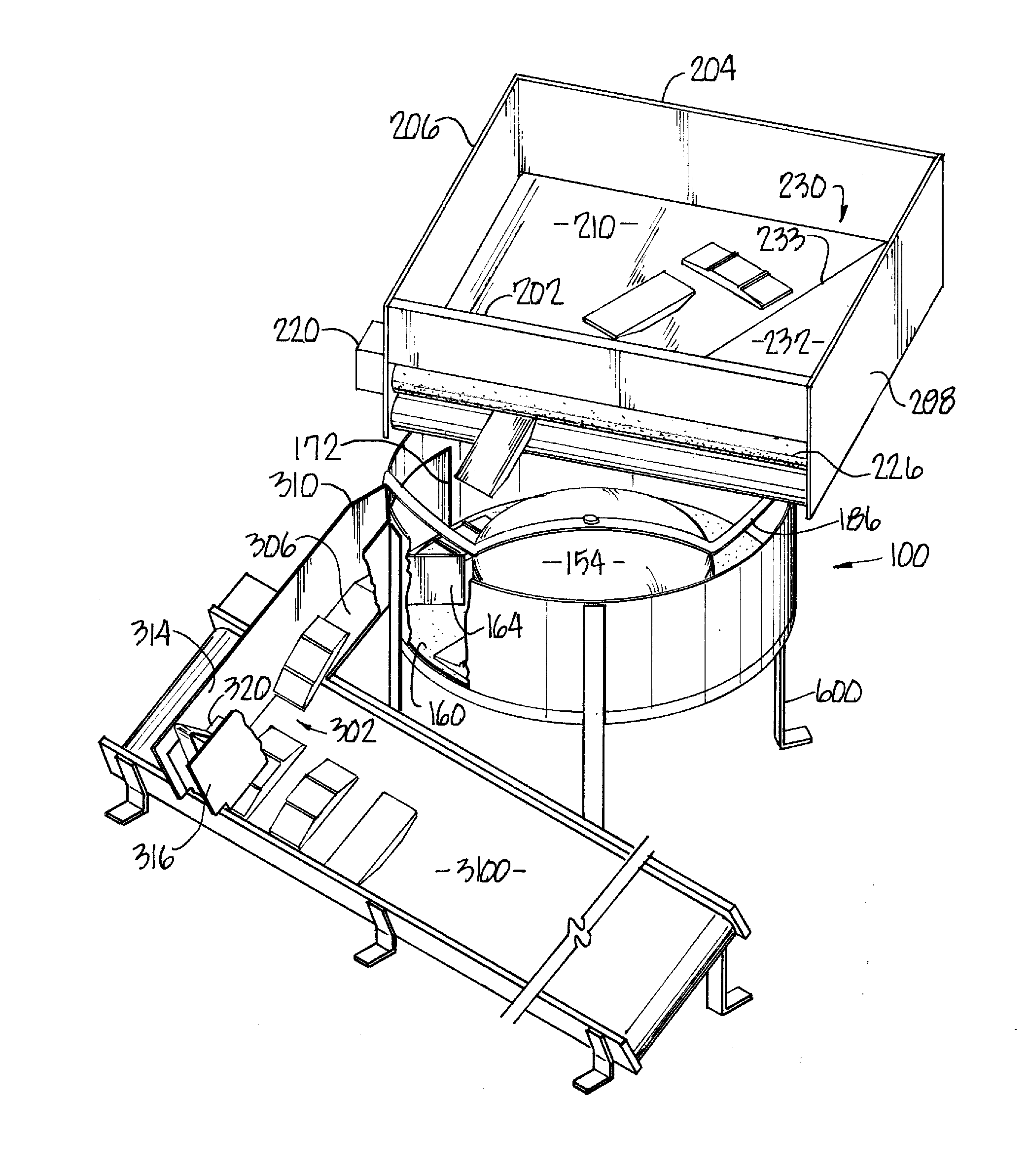
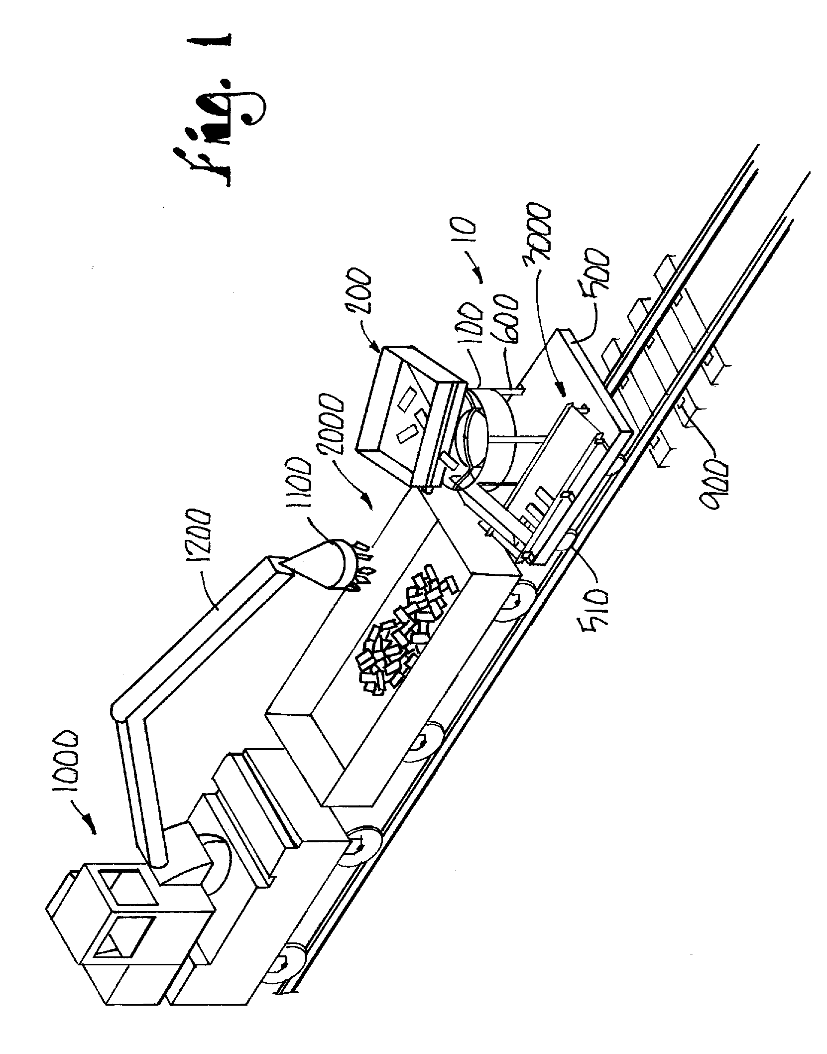
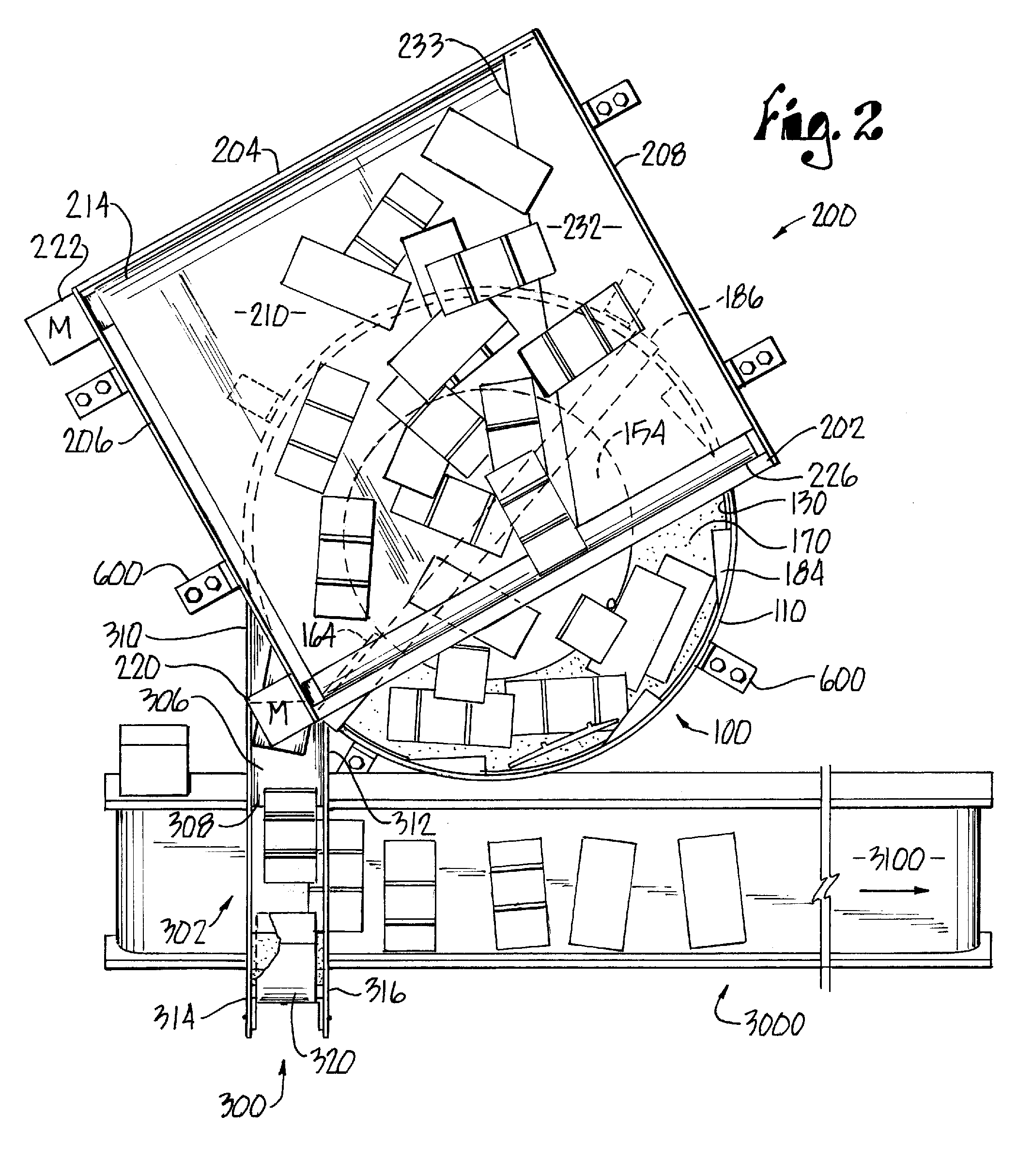
[0027]Turing more particularly to the drawings, FIGS. 5-6 show a tie plate 900 as having a rectangular configuration with the width extending between the field 910 and gage 920 ends. FIG. 1 diagrammatically shows the singularization device 10 as used with a loader car 1000. One type of loader car is shown in U.S. Pat. No. 7,421,952 owned by T. C. Taylor, which is fully incorporated by reference herein. The loader 1000 is utilized with a gondola car 2000 holding a plurality of tie plates therein. A magnet 1100, located at the end of the loader boom 1200, picks up a plurality of tie plates 900 from gondola 2000 for downstream delivery to the singularization device 10 as to be described. The device 10 receives a plurality of tie plates for generally singularizing and orienting the tie plates for downstream delivery. One form of a downstream device is the straight line conveyor 3000 which receives the oriented tie plates on a sequential basis.

[0028]The now preferred embodiment of the de...


PUM


Abstract

A device for sorting railroad tie plates comprises hopper, singulator and chute assemblies mounted to a main frame capable of rolling movement along a railroad track. The device receives a plurality of tie plates from an upstream supply, e.g., a railroad gondola, and deposits the tie plates on the hopper assembly positioned above the singulator. Upon discharge from the hopper the tie plates are directed onto a central hub for guidance into a rotating track within the housing. The track width is selected so that the field and gage ends transverse the track upon the tie plates falling flat onto the track. Structure projects into the track to tip over the tie plates to a flat position during track rotation. Rotation of the track moves the tie plates towards a baffled opening for discharge from the opening. A chute assembly receives the tie plates and maintains the tie plate orientation for delivery to downstream devices, such as a conveyor belt. Upon rolling movement of the main frame tie plates are sequentially deposited along the course of the railroad track to enhance railroad track maintenance.

Description

BACKGROUND OF THE INVENTION[0001]This invention relates to a device for positioning tie plates along a railroad track and, more particularly, to a device which orients tie plates into a desired position for downstream delivery and ultimate deposit along a railroad track.[0002]Railroad tracks comprise two steel rails transversing spaced-apart railroad ties. Atop each tie is a tie plate which connects each rail to the underlying tie. Each tie plate is generally rectangular in configuration having a field end position outside the rail and a gage end inside the rail. The width of the tie plate is defined as a distance between these ends. The tie plates can vary in dimension and weight with most tie plates having a dimension of 7¾″ (L)×14¾″ (W) and weighing approximately 23 pounds, or 8″ (L)×18″ (W) and weighing approximately 35 pounds.[0003]One phase of railroad track maintenance is replacement of railroad ties. As such, there is a need for delivery of not only the railroad ties but als...

Claims


Application Information

Patent Timeline
IPC IPC(8): E01B29/32
CPCE01B29/32
Inventor BUCKLEY, STEPHEN PHILIPGRAHAM, STEVEN D.MANSHEIM, JAMES SPENCER
Owner TAYLOR TIMOTHY CHARLES
Why Eureka
Try Eureka