
Plasma Cutter Having High Power Density
a plasma cutter and power density technology, applied in plasma welding equipment, welding equipment, manufacturing tools, etc., can solve the problems of affecting the performance of the system, relatively low switching frequency and low power density, and adding weight, size, and cost to the plasma cutting system
- Summary
- Abstract
- Description
- Claims
- Application Information
AI Technical Summary
Benefits of technology
Problems solved by technology
Method used
Image

Examples
Embodiment Construction
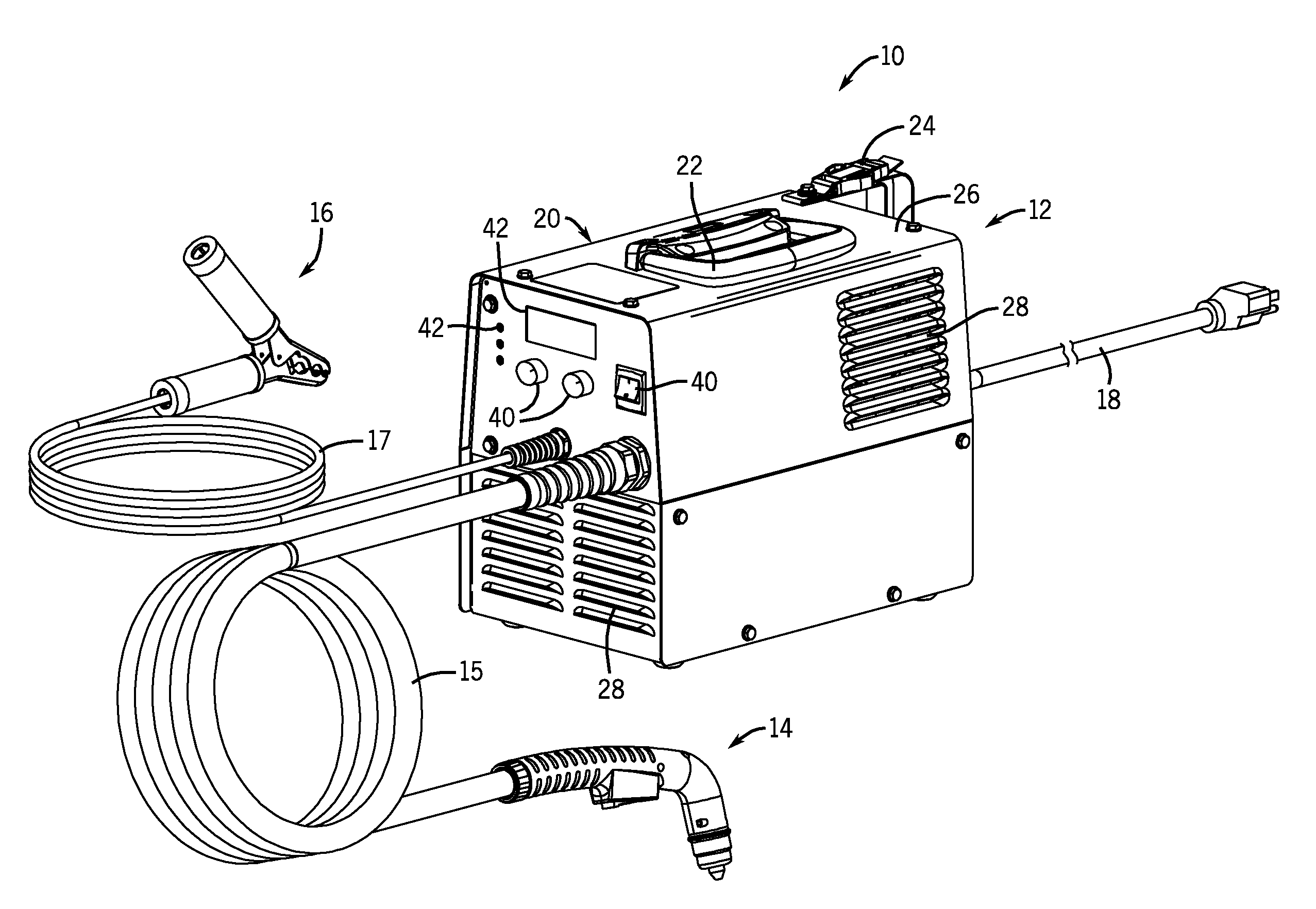
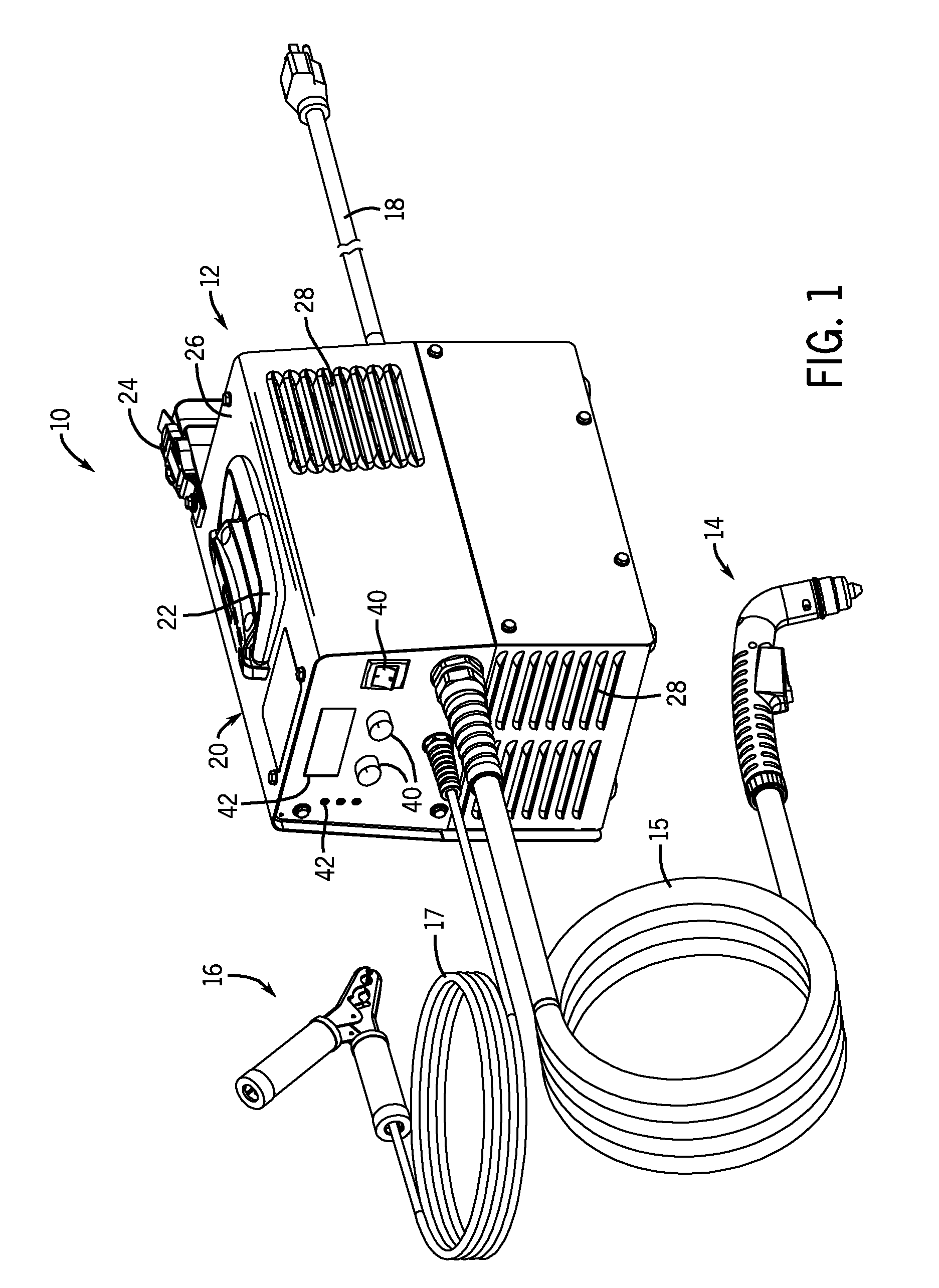
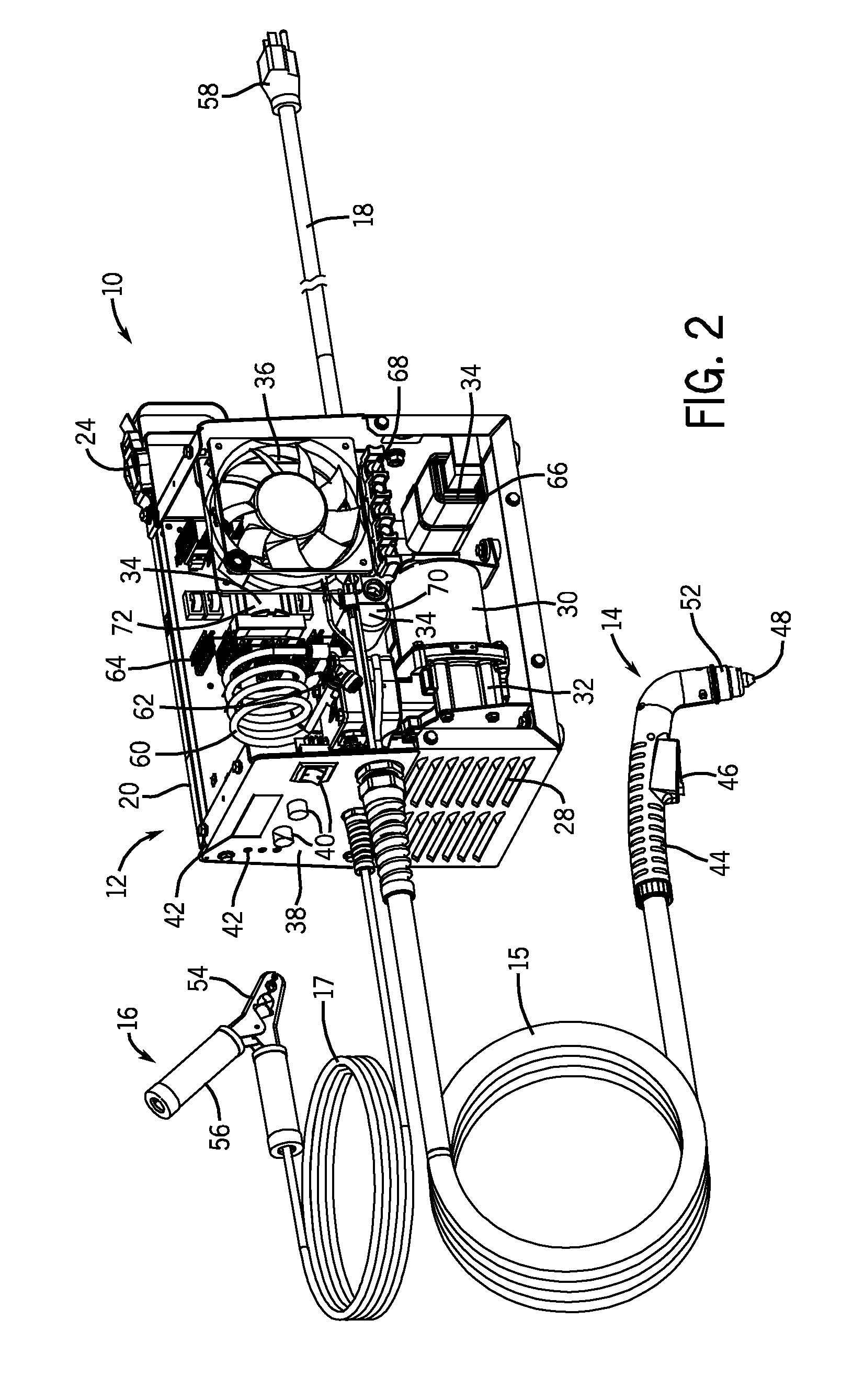
[0014]Referring now to the drawings, FIGS. 1 and 2 are partial perspective views illustrating an embodiment of a portable plasma cutting system 10 having a high power density. For example, one embodiment of the system 10 has 2.6 W per cubic inch and 103.4 W per pound. The system 10 may include high-frequency (e.g., greater than 200 kHz) power converters, foil wound transformers, and / or planar transformers to achieve such high power densities. Specifically, FIG. 1 illustrates the system 10 with access panels completely assembled to close internal components, whereas FIG. 2 illustrates an entire side panel assembly removed to provide a better view of the internal features and components of the system 10. As discussed in further detail below, embodiments of the system 10 may include a printed circuit board (PCB) having components for a main power converter and a motor power converter mounted to the PCB.
[0015]The illustrated plasma cutting system 10 includes a torch power unit 12 couple...
PUM
| Property | Measurement | Unit |
|---|---|---|
| Power | aaaaa | aaaaa |
| Power | aaaaa | aaaaa |
| Power | aaaaa | aaaaa |
Abstract
Description
Claims
Application Information