Split ring for a rotary part of a turbomachine

Active Publication Date: 2009-08-27
SN DETUDE & DE CONSTR DE MOTEURS DAVIATION S N E C M A
View PDF5 Cites 15 Cited by
  • Summary
  • Abstract
  • Description
  • Claims
  • Application Information

AI Technical Summary

Benefits of technology

[0006]A particular object of the invention is to provide a solu

Problems solved by technology

The operation of the turbomachine gives rise to micro-movements and rubbing between the ring and the annular groove in the rotor, thereby dissipating energy and at least partially damping the vibratory phenomena and the instabilities that give rise to the micro-movements and the rubbing of the ring.
Nevertheless, the elastic deformation of the ring in the groove is not uniform over its entire circumferential extent, which gives rise to bending that is substantially zero at the ends of the ring and that increases towards the portion of the ring that is diametrically opposite to split.
Thus, when the ring is mounted in the annular groove, the lack of bending of its end portions does not enable them to

Method used


Image

  • Split ring for a rotary part of a turbomachine
  • Split ring for a rotary part of a turbomachine
  • Split ring for a rotary part of a turbomachine

Examples


Example

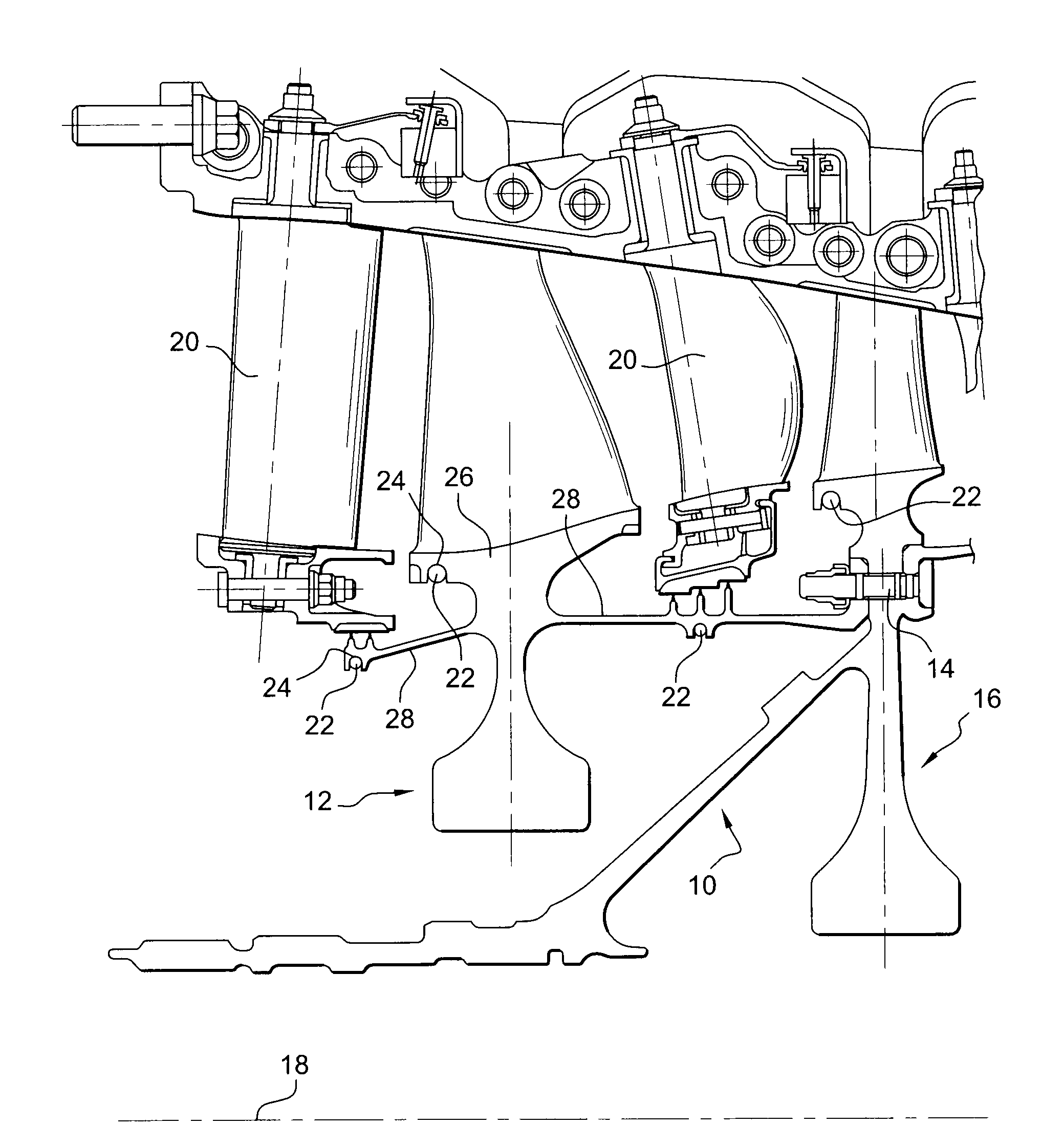
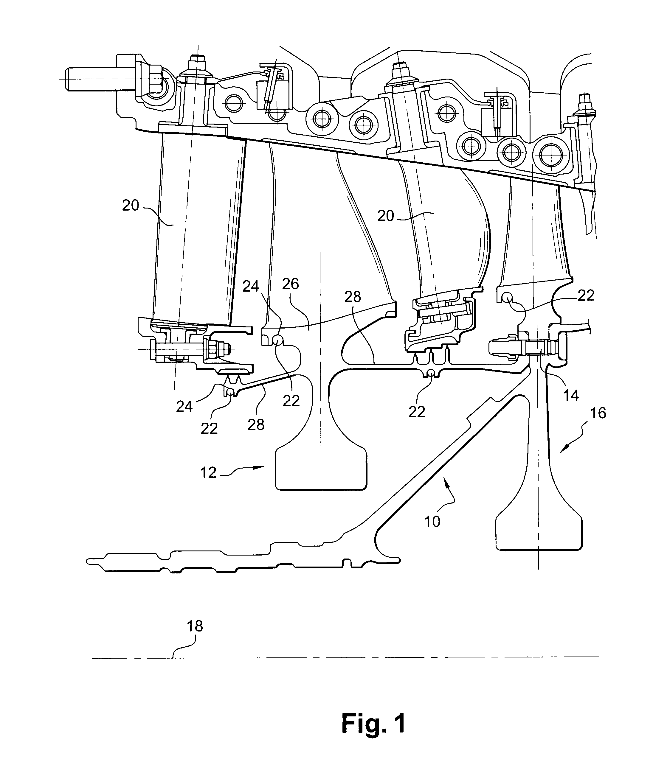
[0022]FIG. 1 shows a portion of a high-pressure compressor of a turbojet, the compressor comprising a rotor 10 with a one-piece bladed disk 12 secured by bolts 14 to another one-piece bladed disk 16 driven in rotation by a shaft (not shown) of axis 18, the high-pressure compressor also comprising stages of stationary nozzle vanes 20 disposed in alternation with the rotor disks 12 and 16, the rotor disks being fitted with vibration damper rings 22 that are mounted in annular grooves 24 formed in the platforms 26 of the disks 12, 16 and in cylindrical walls 28 secured to the disks.

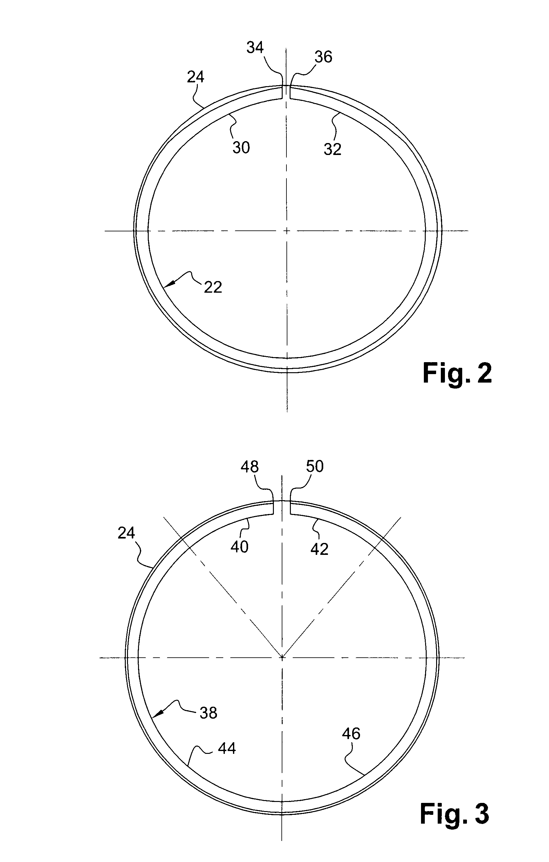
[0023]The rings 22 are split, and in the free state each of them presents a radius greater than the mean radius of the bottom of the annular groove 24 in which it is to be inserted. Prior to being mounted in a groove 24, elastic stress is applied to the ring 22 in order to close it up and reduce its radius for the purpose of inserting it in the groove 24. When in place in the groove, the ring 22 relaxes and ...


PUM


Abstract

A split ring for mounting with elastic prestress in an annular groove of a rotary part of a turbomachine and having, in the free state, a diameter that is greater than the diameter of the groove, is remarkable in that, in the free state and without stress, the end portions of the ring are circular arcs having a radius of curvature that is substantially equal to the radius of curvature of the annular groove.

Description

FIELD OF THE INVENTION [0001]The present invention relates to a ring for mounting on a turbomachine rotor element and that is subjected to a centrifugal force field in operation, the ring serving for example to retain a member, to damp vibration, or to provide sealing.BACKGROUND OF THE INVENTION [0002]By way of example, it is known to damp the vibration of a turbomachine rotor element by means of a metal split ring mounted with elastic stress in an annular groove of a rotor element, the opening of the groove facing towards the axis of rotation of the rotor. The split ring in the free state without stress presents an outer diameter greater than the diameter of the bottom of the groove, and it is tightened up in order to reduce its radius of curvature so as to enable it to be mounted in the groove and exert pressure on the bottom thereof.[0003]The operation of the turbomachine gives rise to micro-movements and rubbing between the ring and the annular groove in the rotor, thereby dissi...

Claims


Application Information

Patent Timeline
IPC IPC(8): F01D5/30
CPCF01D5/10Y10S416/50F05D2260/96F16B21/18
Inventor CLOAREC, YVON
Owner SN DETUDE & DE CONSTR DE MOTEURS DAVIATION S N E C M A
Why Eureka
Try Eureka