System providing braking in a gas turbine engine in the event of the turbine shaft breaking

Active Publication Date: 2009-05-21
SN DETUDE & DE CONSTR DE MOTEURS DAVIATION S N E C M A
View PDF9 Cites 10 Cited by
  • Summary
  • Abstract
  • Description
  • Claims
  • Application Information

AI Technical Summary

Benefits of technology

[0006]The present invention is oriented toward a simple, effective and inexpensive solution for reducing the rotational speed, in a gas tu

Problems solved by technology

This speed is the speed liable to

Method used


Image

  • System providing braking in a gas turbine engine in the event of the turbine shaft breaking
  • System providing braking in a gas turbine engine in the event of the turbine shaft breaking
  • System providing braking in a gas turbine engine in the event of the turbine shaft breaking

Examples


Example

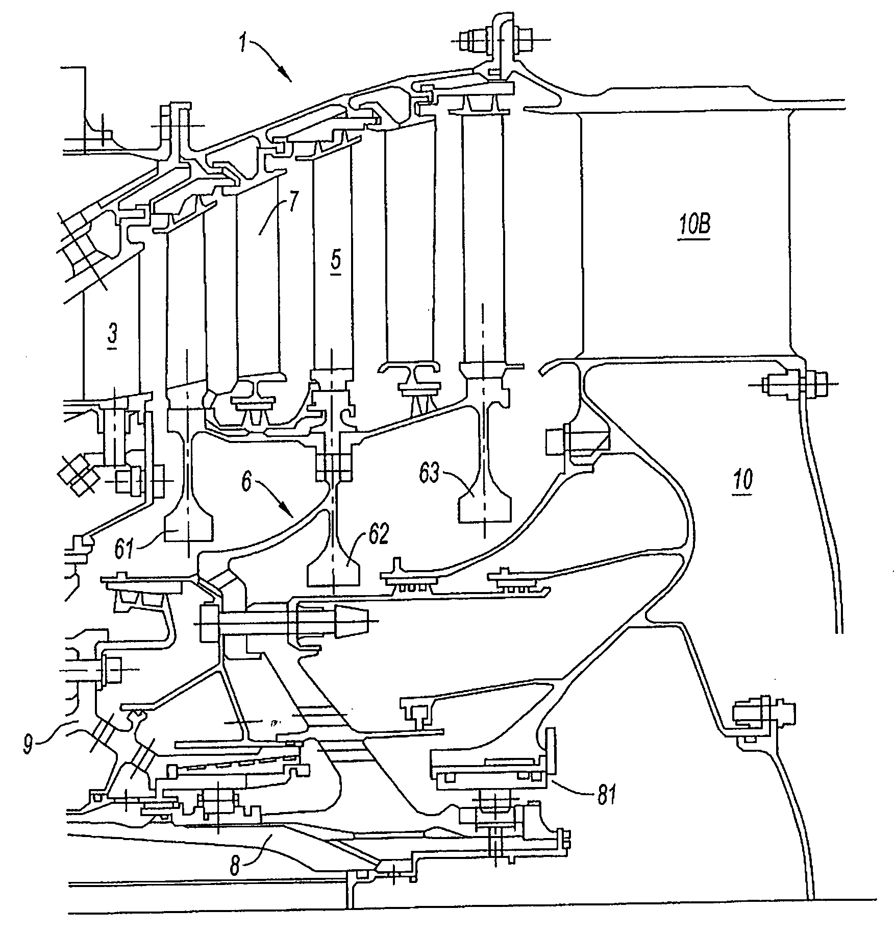
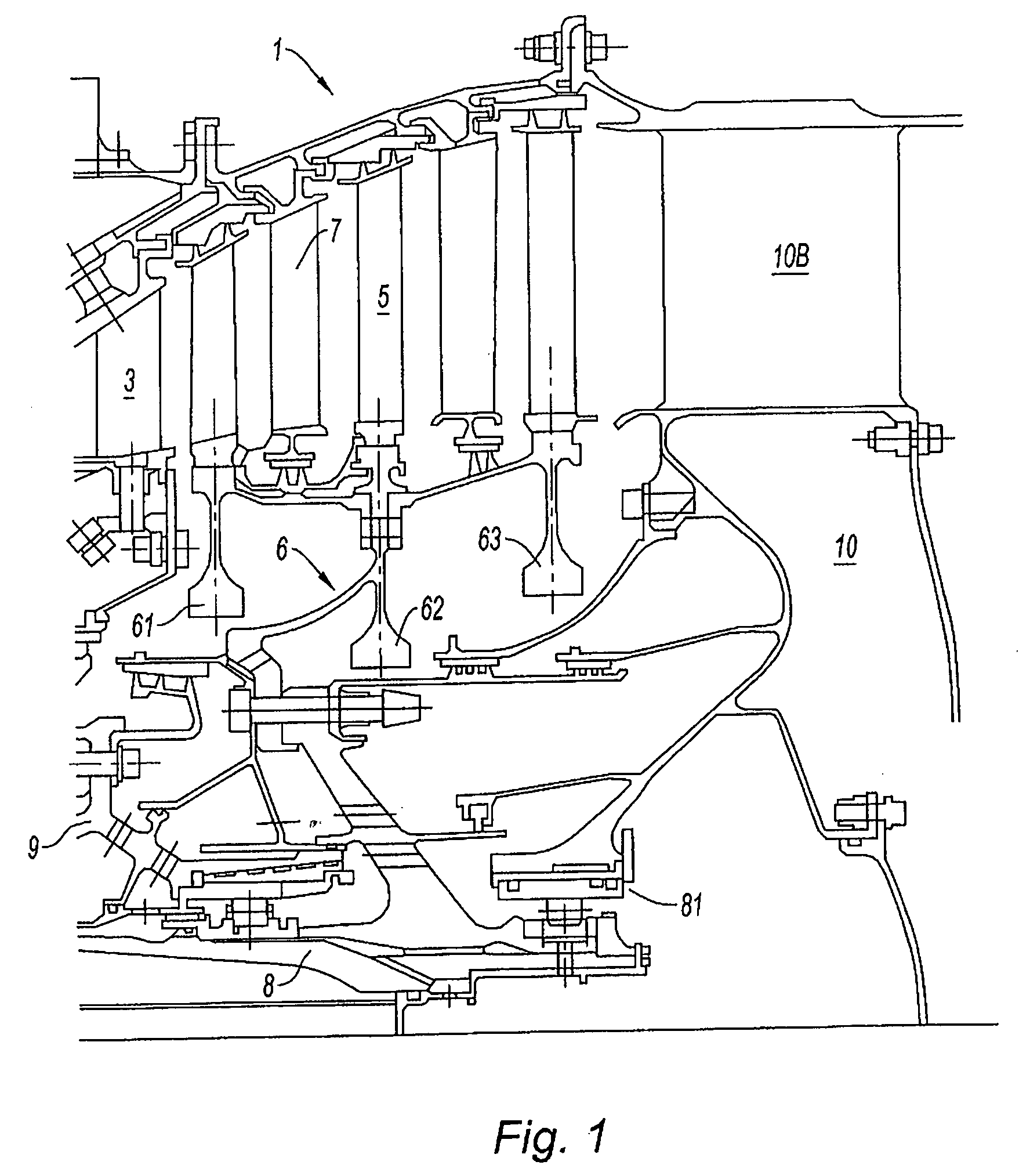
[0017]FIG. 1 shows part of the turbine section 1 of a gas turbine engine. In a twin spool bypass engine, the turbine section 1 comprises an upstream high-pressure turbine, not visible in the figure, which receives the hot gases from the combustion chamber. The gases, having passed through the blading of the high-pressure turbine impeller, are directed through a set of fixed guide vanes 3, on to the low-pressure turbine section 5. This section 5 is made of a rotor 6 here in the form of a drum from an assembly of several bladed disks 61, 62, 63, in this example three bladed disks. The blades, which comprise a vane and a root, are mounted, generally individually, at the periphery of the disks in housings made in the rim. Sets of fixed guide vanes 7 are interposed between the turbine stages, each having the purpose of suitably directing the gas stream with respect to the moving blade downstream. This assembly forms the low-pressure turbine section 5. The rotor 6 of the low-pressure turb...


PUM

PropertyMeasurementUnit
Currentaaaaaaaaaa
Currentaaaaaaaaaa
Pressureaaaaaaaaaa

Abstract

The present invention relates to a device for, in a gas turbine engine, braking a turbine comprising a rotor driving a shaft capable of rotating with respect to a stator in the event of said shaft breaking. The device is one which comprises a first braking member (110) provided with at least one abrasive element (110A) and a second braking member (120) comprising a ring-shaped element (120A) made of a material capable of being eroded by the abrasive element (110A), the two braking members being secured one of them to the rotor and the other to the stator and coming into contact with one another through axial displacement of the rotor once the shaft has broken, the abrasive element (110A) of the first braking member (110) eroding the ring-shaped element (120A) of the second braking member (120).

Description

BACKGROUND OF THE INVENTION[0001]The present invention relates to the field of gas turbine engines and, in particular, that of multiple flow turbojet engines and relates to a system that, in the event that a shaft of the machine breaks, allows the machine to be stopped in the shortest possible time.[0002]In a multiple flow turbofan jet engine, the fan is driven by the low-pressure turbine. When the shaft connecting the fan rotor to the turbine rotor breaks, the resistive torque on the turbine is suddenly removed although the flow of driving gas continues to transmit its energy to the rotor. This results in a rapid increase in the rotational speed of the rotor which is liable to reach the limit that it can withstand and shatter, with the ensuing catastrophic consequences that this has.DESCRIPTION OF THE PRIOR ART[0003]It has been proposed that the supply of fuel to the combustion chamber be interrupted in order to eliminate the source of energy via which the rotor is accelerated. One...

Claims


Application Information

Patent Timeline
IPC IPC(8): F01D21/14
CPCF01D21/006F05D2260/902F05D2230/90F05D2300/21F05D2300/601F05D2300/2118F05D2300/44F05D2300/603F05D2300/611F05D2300/614F05D2300/2102
Inventor BART, JACQUES RENEESCURE, DIDIER RENE ANDREMONS, CLAUDE MARCELROUSSELIN, STEPHANE
Owner SN DETUDE & DE CONSTR DE MOTEURS DAVIATION S N E C M A
Why Eureka
Try Eureka