Arrangement for and method of accurately aiming at direct part markings prior to being imaged and electro-optically read

an arrangement and direct part technology, applied in the field of arrangement and method of accurately aiming at direct part markings prior to being imaged and electro-optically read, can solve the problems of difficult use of imaging readers, especially handheld readers, for reliably reading dpm codes on workpieces, and inability to achieve accurate aiming, so as to achieve the effect of easy and rapid aiming

Inactive Publication Date: 2009-09-03
SYMBOL TECH INC
View PDF10 Cites 28 Cited by
  • Summary
  • Abstract
  • Description
  • Claims
  • Application Information

AI Technical Summary

Benefits of technology

[0011]Thus, the present invention proposes a large aiming pattern in which the outer bright region is highly visible to the operator. The annulus configuration is preferred, because it has no preference for orientation of the aiming pattern in any direction, e.g., up-and-down or side-to-side. Th

Problems solved by technology

Despite the ability to control very tight specifications on element size, width, spacing and so on, the lack of sharp contrast of machine-readable optical DPM codes directly marked on metal, plastic, leather, glass, etc., workpieces prevents traditional moving laser beam readers from electro-optically reading the DPM codes reliably.
Yet, the use of imaging readers, especially handheld readers, for reading DPM codes on workpieces has proven to be challenging.
Contrast is still often less than desirable.
In addition, aiming the handheld imaging readers at the DPM codes, prior to reading the DPM codes, has proven to be difficult.
Unlike mach

Method used


Image

  • Arrangement for and method of accurately aiming at direct part markings prior to being imaged and electro-optically read
  • Arrangement for and method of accurately aiming at direct part markings prior to being imaged and electro-optically read
  • Arrangement for and method of accurately aiming at direct part markings prior to being imaged and electro-optically read

Examples


Embodiment Construction

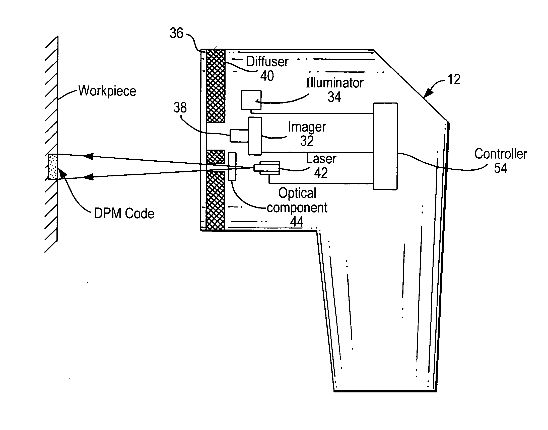
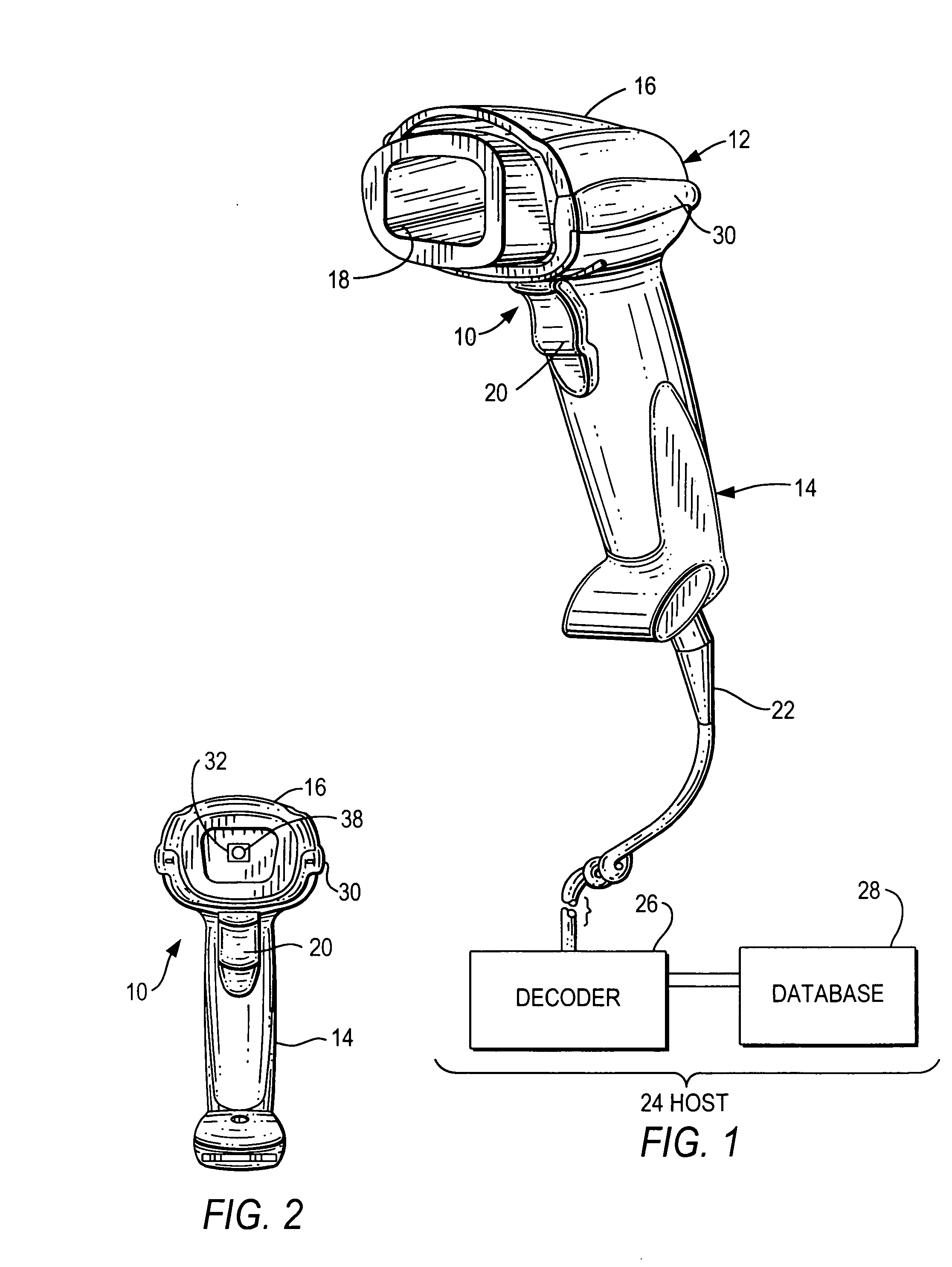
[0019]Reference numeral 10 in FIGS. 1-2 generally identifies a handheld, portable imaging reader for electro-optically reading indicia, such as DPM codes on workpieces. The reader 10 includes a housing 12 in which various aiming, illuminating, and image capture systems, as described below, are incorporated. The housing 12 includes a generally elongated handle or lower handgrip portion 14 and a barrel or upper body portion 16 having a front end region at which an open face 18 is located. The cross-sectional dimensions and overall size of the handle 14 are such that the reader can conveniently be held in an operator's hand. The body and handle portions may be constructed of a lightweight, resilient, shock-resistant, self-supporting material such as a synthetic plastic material. The plastic housing may be injection molded, but can be vacuum-formed or blow-molded to form a thin hollow shell which bounds an interior space whose volume is sufficient to contain the various systems of this ...


PUM


Abstract

Aiming of an imaging reader at direct part markings (DPM) on workpieces is enhanced by emitting an aiming light beam during aiming, and by optically modifying the aiming light beam during the aiming to generate an aiming light pattern having an outer bright region illuminated by the aiming light beam and visible to an operator to enable the operator to manually position the bright region to entirely surround at least part of the DPM, and an inner dark region not illuminated by the aiming light beam and surrounded by the bright region. The dark region contains the part of the DPM code to be imaged and read by the reader after the aiming.

Description

BACKGROUND OF THE INVENTION[0001]Direct part marking (DPM) allows workpieces to be directly marked, identified and traced to their origin, and its use is growing in the automotive, aerospace, electronics, medical equipment, tooling, and metalworking industries, among many others. Despite the ability to control very tight specifications on element size, width, spacing and so on, the lack of sharp contrast of machine-readable optical DPM codes directly marked on metal, plastic, leather, glass, etc., workpieces prevents traditional moving laser beam readers from electro-optically reading the DPM codes reliably. These moving beam readers emit a laser beam, which reflects off the highly reflective, typically non-planar, metal or glass, workpieces as bright light.[0002]To counter a variety of problems, such as lack of contrast, difficulty of maintaining precise element specifications, limited available marking areas, and a large amount of data to be encoded, the art proposed the use of ma...

Claims


Application Information

Patent Timeline
IPC IPC(8): G06K7/10
CPCG06K7/10732
Inventor JOSEPH, EUGENELIU, RONG
Owner SYMBOL TECH INC
Why Eureka
Try Eureka