
Suspension arm type odontoid guide needle sighting device

A cantilever type, aiming technology, applied in medical science, surgery and other directions, can solve the problems of internal fixation screw offset, cannot be connected in series, affecting the operation effect, etc., and achieves the effect of reliable fixation, easy adjustment and accurate aiming.

Inactive Publication Date: 2013-12-18
徐兆万
View PDF4 Cites 17 Cited by
  • Summary
  • Abstract
  • Description
  • Claims
  • Application Information

AI Technical Summary

Problems solved by technology

[0002] Cannulated screw fixation for odontoid fractures through the anterior cervical approach has a history of 20 years. It is mainly used for Anderson type Ⅱ and Anderson superficial Ⅲ odontoid fractures. The operation is difficult, and inaccurate positioning of the hollow screw will lead to deviation of the internal fixation screw and tooth fracture. Poor healing or malunion of condylar fractures, even stabbing dura mater and nerves
When performing odontoid fracture screw fixation, the first step is to penetrate the Kirschner wire, because the Kirschner wire is thin and long, it is difficult to grasp the direction of needle insertion, and deviations are prone to occur
If it is necessary to correct and re-insert the needle, it is often difficult to avoid the original needle path, resulting in poor internal fixation position and effect
In 2009, the inventor applied for an invention patent with a patent number of 200910020476.0 and an invention title of an Odontoid Guide Pin Sight, which disclosed an Odontoid Guide Pin Sight, which included a connecting beam, and one end of the connecting beam was inserted into the It is equipped with a hollow guide drill for setting the guide pin, and the connecting beam at the end is equipped with a hollow guide drill locking device; in the middle of the connecting beam, there is a universal adjuster that can be locked on the connecting beam, and the universal adjustment An adjustable fixed rod is inserted in the device. When using the above-mentioned structure of the tooth process guide needle sight, the fixed rod is fixed to the C4 or C5 vertebral body, and the universal adjuster is used to rotate around the connecting beam, and the two buckles are fixed around the beam. Rotate the rod to adjust the entry angle of the Kirschner wire and the drilling angle of the hollow guide drill, which has the following disadvantages: 1. It is difficult to fix the fixed rod accurately, which will lead to instability of the whole set of sights, and easily cause inaccurate positioning of the hollow screw ; 2. Due to the small diameter of the hollow guide drill, it is easy to vibrate during the drilling and reaming process, which may easily cause damage to the surrounding soft tissue and affect the surgical effect; Repeated twisting and adjustment, three-dimensional angle adjustment is very difficult, prolonging the operation time and increasing the difficulty of the operation; 4. It is necessary to cooperate with X-ray perspective and use the doctor's technology to determine the drilling depth of the hollow guide drill during the operation If it is too deep, it is easy to damage the medulla oblongata, and if it is too shallow, it cannot be connected in series, which increases the difficulty of surgery

Method used


Image

  • Suspension arm type odontoid guide needle sighting device
  • Suspension arm type odontoid guide needle sighting device
  • Suspension arm type odontoid guide needle sighting device

Examples


Embodiment Construction

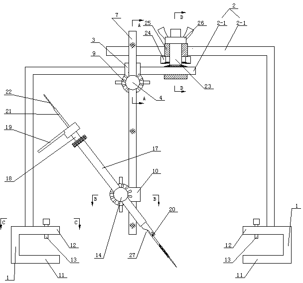
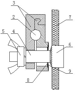
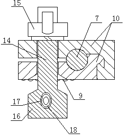
[0019] Referring to the accompanying drawings, the cantilever type denticule guide pin collimator includes two lower connecting seats 1 oppositely arranged, and the two lower connecting seats 1 respectively have an upper pressing plate 11 and a lower supporting plate 12 which are parallel up and down and arranged correspondingly. A plurality of jacking bolts 13 are screwed on the plate 11, and a door-shaped cantilever 2 with a circular cross section is fixedly connected between the two opposite upper pressing plates 11, and the door-shaped cantilever 2 is respectively fixed on the two upper pressing The two sections of L-shaped cantilever 2-1 are composed of two sections of L-shaped cantilevers 2-1 on the back plate 11. The opposite extending ends of the two L-shaped cantilevers 2-1 are connected by sliding and rotating connecting blocks. The mutual displacement of -1 controls the length of the gate-shaped cantilever 2, and any section of the L-shaped cantilever 2-1 can be rota...


PUM


Abstract

The invention discloses a suspension arm type odontoid guide needle sighting device, which comprises two lower connecting seats, wherein the two lower connecting seats are respectively provided with an upper pressing plate and a lower support plate, each upper pressing plate is screwed with a plurality of jacking bolts, an n-shaped suspension arm is fixedly connected between the two opposite upper pressing plates, and is sheathed with an upper clamping block, the upper clamping block is provided with an upper adjusting bolt column in a penetrating way, one end of the upper adjusting bolt column is screwed with an upper adjusting nut, the other end of the upper adjusting bolt column is provided with a conical penetrating column, the surface of the upper clamping block is provided with a conical annular groove, the lower part of an upper adjusting rod is sheathed with a lower clamping block, the lower clamping block is provided with a lower adjusting bolt column in a penetrating way, one end of the lower adjusting bolt column is screwed with a lower adjusting nut, the other end of the lower adjusting bolt column is provided with a lower penetrating column, the lower penetrating column is provided with a lower penetrating hole, a working sleeve tube penetrates into the lower penetrating hole, the interior of the working sleeve tube is rotationally connected with a sighting sleeve tube, the upper end of the sighting sleeve tube is provided with a handle, and the lower end of the sighting sleeve tube is provided with clamping teeth. The device has the advantages that the fixing is reliable, the sighting is accurate, the adjustment is simple and convenient, and the reaming depth is conveniently and accurately controlled.

Description

technical field [0001] The invention belongs to the technical field of orthopedic surgery medical instruments, and in particular relates to a cantilever type dento-process guide pin aimer. Background technique [0002] Cannulated screw fixation for odontoid fractures through the anterior cervical approach has a history of 20 years. It is mainly used for Anderson type Ⅱ and Anderson superficial Ⅲ odontoid fractures. The operation is difficult, and inaccurate positioning of the hollow screw will lead to deviation of the internal fixation screw and tooth fracture. Poor healing or malunion of condylar fractures, and even stabbing of the dura mater and nerves. When performing internal fixation of odontoid fractures with screws, the first step is to penetrate the Kirschner wires. Because the Kirschner wires are thin and long, it is difficult to grasp the direction of needle insertion, and deviations are prone to occur. If it is necessary to correct and re-insert the needle, it is...

Claims


Application Information

Patent Timeline
Patent Type & Authority Applications(China)
IPC IPC(8): A61B17/90
Inventor 徐兆万于明东刘伟强
Owner 徐兆万
Learn More