Speaker assembly with directional adjustability

a technology of directional adjustment and speaker assembly, which is applied in the direction of transducer details, electrical apparatus casings/cabinets/drawers, transducer details, etc., can solve the problems of limited rotation, pressure fit components that do not allow for adjustment of tension during assembly process, and speaker positions that cannot be firmly locked in pla

Active Publication Date: 2009-11-12
STRUCTURED CABLE PROD INC
View PDF36 Cites 20 Cited by
  • Summary
  • Abstract
  • Description
  • Claims
  • Application Information

AI Technical Summary

Problems solved by technology

These pressure fit components do not allow for adjustment of the tension during the assembly process, either during manufacturing or in the field during installation.
None of these assemblies allow the speaker position to be firmly locked in place.
Another problem with prior art adjustable speakers is limited rotation due to internal connecting wires.
However, the foam tends to deteriorate over time, such that the desired position is difficult to maintain.
Prior art adjustable speakers also tend to vibrate out of position after installation, since the speaker is an active device which creates vibration.
Such vibrations may loosen the components, which may result in an undesirable buzz or rattle noise.
The wide variations and ambient temperatures also complicate the long term integrity of the adjustable speakers.
For example, ceiling speakers often are installed with the upper or rear portion exposed to the attic, which may have extreme temperature and humidity swings which create further problems, since the plastic components are hydroscopic.
Cabinet vibrations or inadequate mounting of the driver to the cabinet creates a loss of energy in the performance of the driver, which translates to a muddy mid-range or base response from the speaker.
Prior art adjustable ceiling mount speakers do not lock the driver firmly in the frame or baffle to prevent the undesired effects of vibration and energy loss, and therefore have less than optimal speaker performance.
Some speaker applications have additional vibrations, such as automobiles, trucks, and aircraft, due to movement of the vehicle along the road, through the water, or in the air.
Such exterior vibrations also eventually lead to loosening of the prior art pivot mechanisms for the speakers, which then move from the desired directional setting.

Method used


Image

  • Speaker assembly with directional adjustability
  • Speaker assembly with directional adjustability
  • Speaker assembly with directional adjustability

Examples


Embodiment Construction

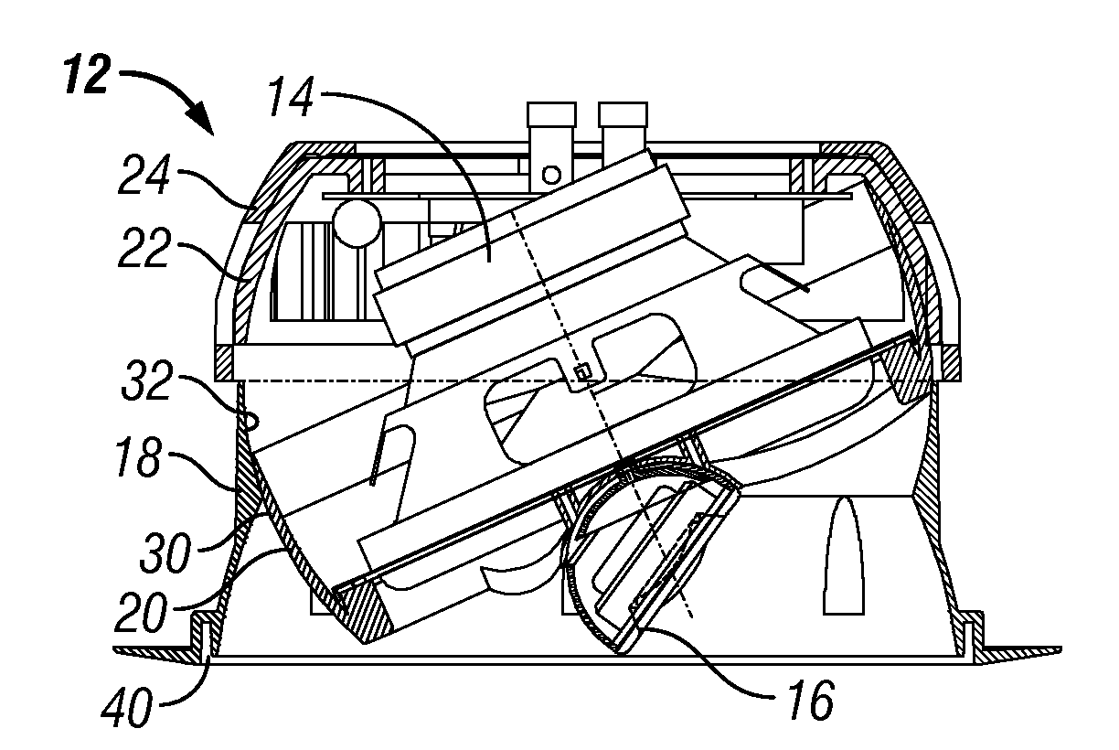
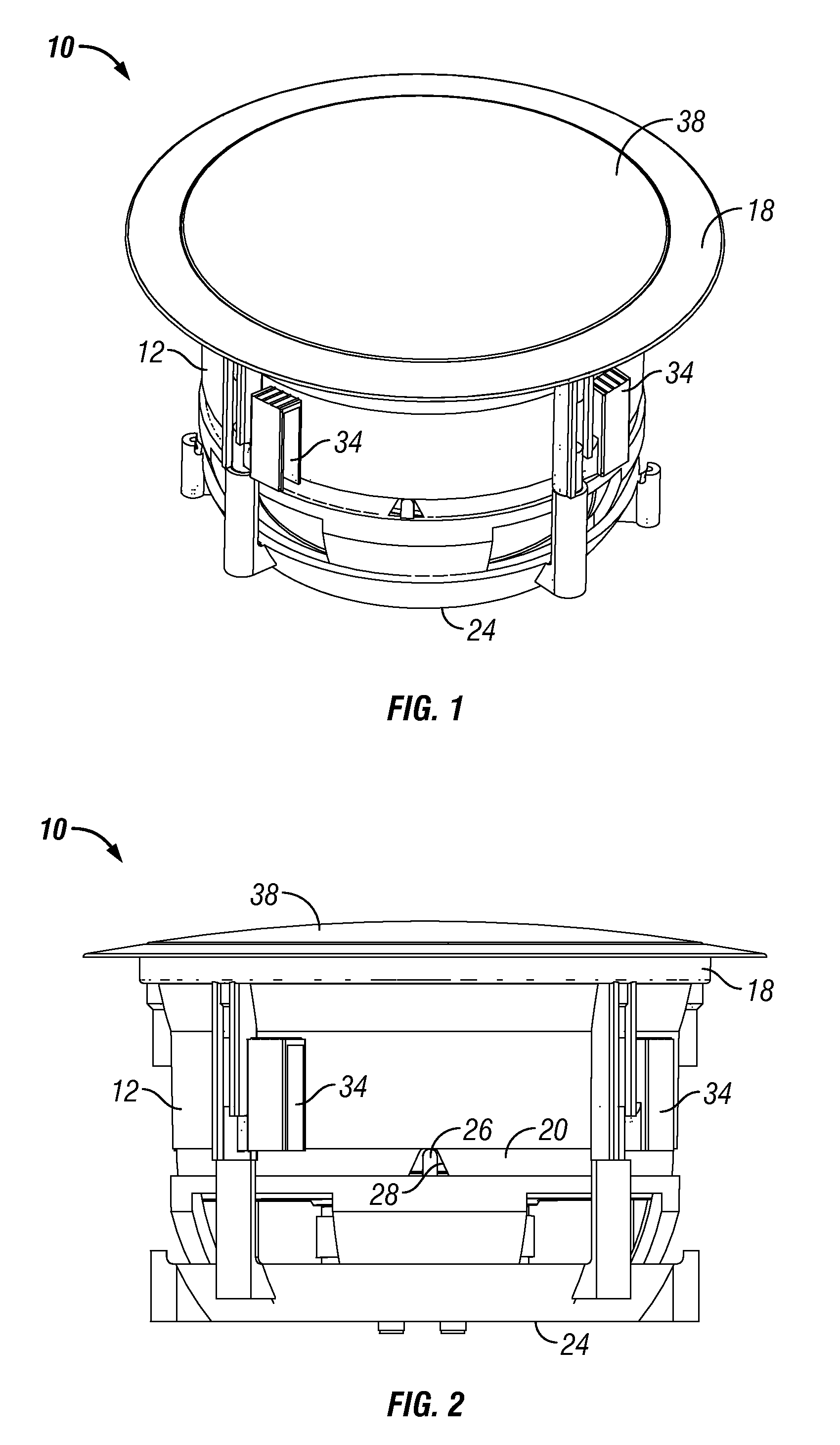
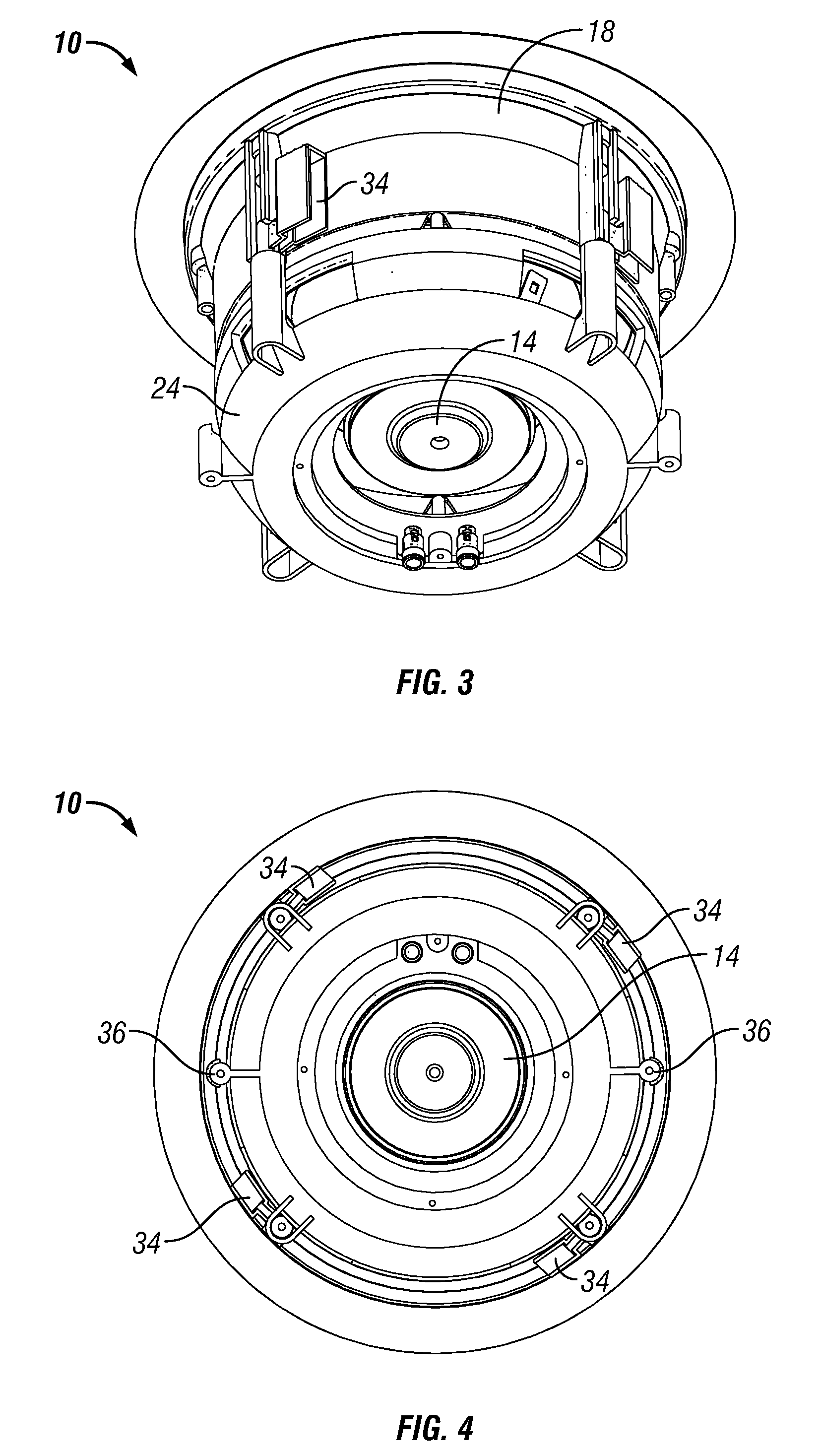
[0038]The speaker assembly of the present invention is generally designated in the drawings by the reference numeral 10. The assembly 10 includes a housing 12, a woofer or driver 14, and a tweeter 16. The housing 12 is designed so as to allow the driver 14 to be tilted and rotated about a center axis of the housing.

[0039]More particularly, the housing 12 includes four primary components, the baffle 18, the swivel 20, the swivel cup 22, and the retainer 24, as best seen in FIGS. 9, 11 and 13. The driver 14 and tweeter 16 are mounted in the swivel 20. The swivel cup 22 includes a pair of ribs 26 (FIGS. 9 and 21) extending downwardly from the opposite sides of the cup 22. The swivel 20 has a pair of recesses 28 (FIGS. 9 and 17) formed on the opposite sides to receive the ribs 26 and pivot about the ribs approximately 30° in either direction. Thus, the total pivotal movement of the swivel 20 relative to the swivel cup 22 is approximately 60°. For example, FIG. 6 shows the swivel 20 and ...


PUM


Abstract

An improved audio speaker assembly is provided for directional adjustability of the woofer or driver. The assembly includes a housing comprising a baffle, a swivel, a swivel cup, and a retainer. The driver is mounted in the swivel. The swivel and swivel cup are mounted between the baffle and the retainer. The swivel is pivotal approximately 60° relative to the swivel cup, and is rotatable 360° relative to the baffle, thereby selectively positioning the driver in a desired direction. A pair of screws extend through the baffle and into the retainer, and can be tightened so as to lock or clamp the swivel and driver in the selected position, and preclude directional movement due to vibrations, temperature, and humidity.

Description

CROSS-REFERENCE TO RELATED APPLICATIONS[0001]This application claims priority under 35 U.S.C. §119(e) to provisional application Ser. No. 61 / 051,027 filed May 7, 2008, herein incorporated by reference in its entirety.BACKGROUND OF THE INVENTION[0002]Ceiling and wall mounted audio speakers are well known in the industry. The earliest ceiling speakers had a fixed orientation such that the woofer and tweeter pointed substantially straight downwardly or outwardly. More recently, speakers have been designed with the pivotal and swivel components for directional adjustment of the woofer and / or tweeter. The orientation of such adjustable speakers generally is maintained by pressure between the components, which often are made of plastic. The various types of pressure couplings differ in the effort or force required to adjust the speaker to the desired position. These pressure fit components do not allow for adjustment of the tension during the assembly process, either during manufacturing ...

Claims


Application Information

Patent Timeline
Patent Type & Authority Applications(United States)
IPC IPC(8): H04R1/02
CPCH04R1/025H04R1/26H04R2499/13H04R2201/021H04R31/006H04R1/24H04R1/323H04R9/063
Inventor MAURER, RONALD D.MCDERMOTT, SEAN P.APGAR, RICHARD P.
Owner STRUCTURED CABLE PROD INC
Why Eureka
Try Eureka